Variable density graphite foam heat sink

a graphite foam and heat sink technology, applied in ceramicware, semiconductor/solid-state device details, other domestic articles, etc., can solve the problems of increasing the amount of heat generated by these components, increasing the amount of heat generated in a smaller volume of space, and damage to equipment components

Inactive Publication Date: 2005-04-28
INTEL CORP
View PDF15 Cites 35 Cited by
  • Summary
  • Abstract
  • Description
  • Claims
  • Application Information

AI Technical Summary

Problems solved by technology

Microprocessors and other electronic circuit components are becoming more and more powerful with increasing capabilities, resulting in increasing amounts of heat generated from these components.
Furthermore, as computer related equipment becomes faster, more and more components are being placed inside equipment, which is also decreasing in size, resulting in additional heat generation in a smaller volume of space.
Increased temperatures can potentially damage the components of the equipment, or reduce the lifetime of the individual components and the equipment.

Method used


Image

  • Variable density graphite foam heat sink
  • Variable density graphite foam heat sink
  • Variable density graphite foam heat sink

Examples


Embodiment Construction

[0010] In the following description, for purposes of explanation and not limitation, specific details are set forth such as particular structures, architectures, interfaces, techniques, etc. in order to provide a thorough understanding of the various aspects of the invention. However, it will be apparent to those skilled in the art having the benefit of the present disclosure that the various aspects of the invention may be practiced in other examples that depart from these specific details. In certain instances, descriptions of well know devices, circuits, and methods are omitted so as not to obscure the description of the present invention with unnecessary detail.

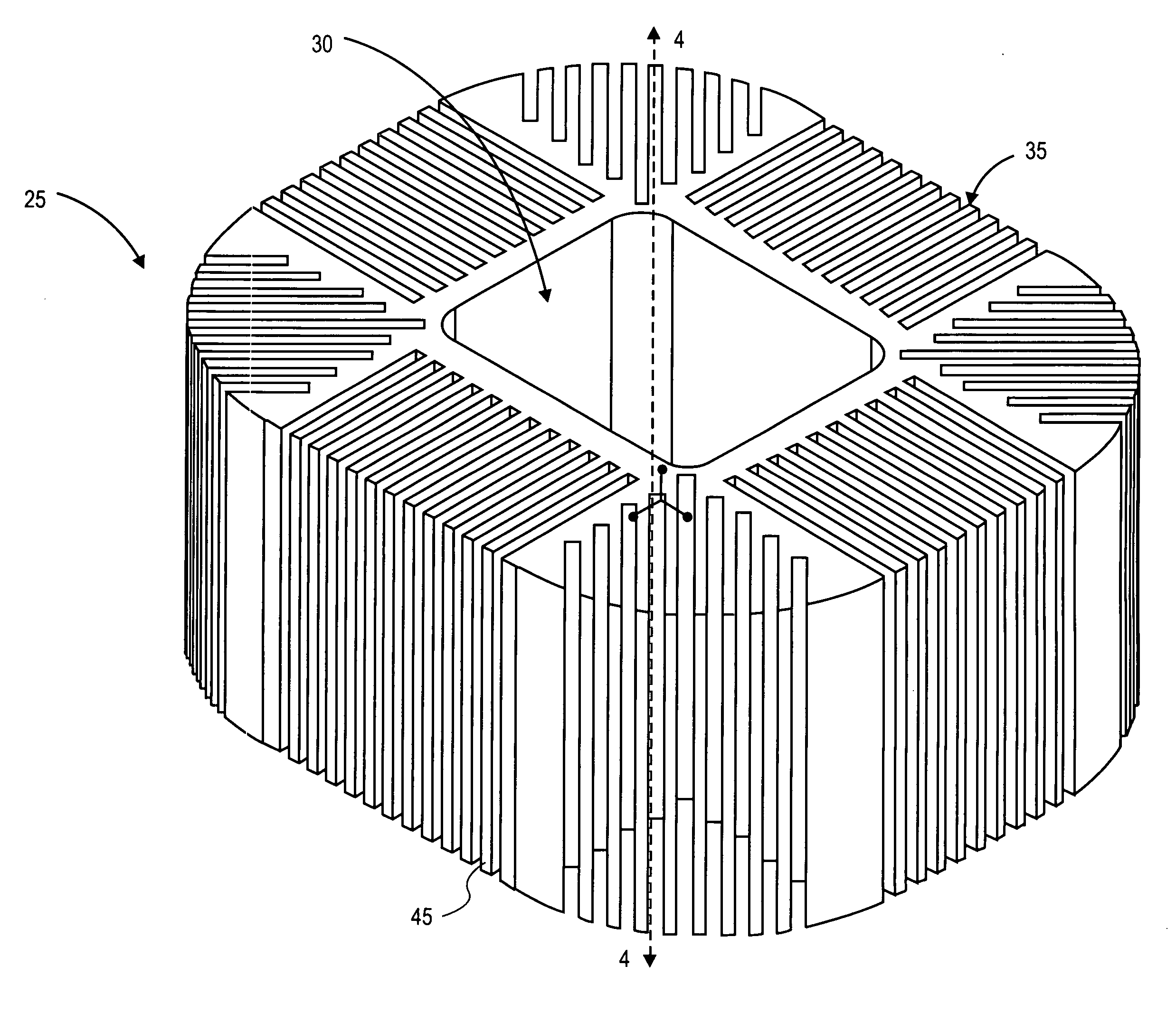
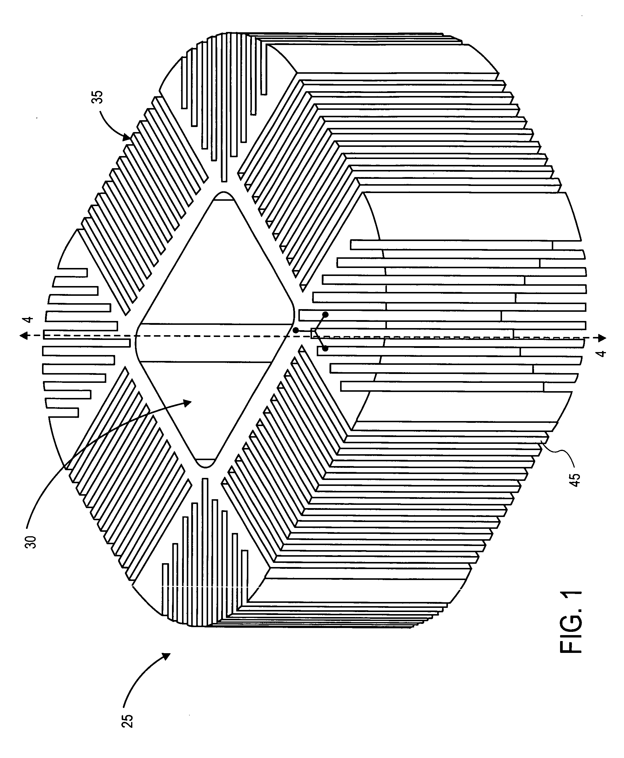
[0011] Graphite foam is a new material developed by scientists at the Oak-Ridge National Lab. The thermal conductivity of 90% graphite foam has been shown to be approximately equal to that of copper, but its density is ⅙th that of copper, making it much lighter than copper for the same volume and thus having better heat ...


PUM

PropertyMeasurementUnit
weightaaaaaaaaaa
weightaaaaaaaaaa
cooling capacityaaaaaaaaaa

Abstract

A heat sink is disclosed for directing heat away from an electronic component dissipating heat. The heat sink includes a thermally conductive base formed of a variable density graphite foam article. This graphite foam heat sink having variable foam densities provides for higher cooling capacity than existing heat sinks.

Description

BACKGROUND INFORMATION [0001] Microprocessors and other electronic circuit components are becoming more and more powerful with increasing capabilities, resulting in increasing amounts of heat generated from these components. Packaged units and integrated circuit die sizes of these components are decreasing or remaining the same, which increases the amount of heat energy given off by the components for a given unit of surface area. Furthermore, as computer related equipment becomes faster, more and more components are being placed inside equipment, which is also decreasing in size, resulting in additional heat generation in a smaller volume of space. Increased temperatures can potentially damage the components of the equipment, or reduce the lifetime of the individual components and the equipment. Therefore, large amounts of heat produced by many such integrated circuits must be dissipated, and therefore must be accounted for in designing the integrated circuit. [0002] For the reason...

Claims


Application Information

Patent Timeline
Patent Type & Authority Applications(United States)
IPC IPC(8): C04B38/00H01L23/367H01L23/373H01L23/427
CPCC04B38/0067C04B2111/00844H01L23/367H01L23/373H01L23/3733H01L2924/0002C04B35/522H01L2924/00
Inventor KABADI, ASHOK N.BRADY, GARY W.DEWEESE, FRANK R.HAMPTON, HARRY L. III
Owner INTEL CORP
Why Eureka
Try Eureka