

Braze alloy
- Summary
- Abstract
- Description
- Claims
- Application Information
AI Technical Summary
Benefits of technology
Problems solved by technology
Method used
Image

Examples
Embodiment Construction
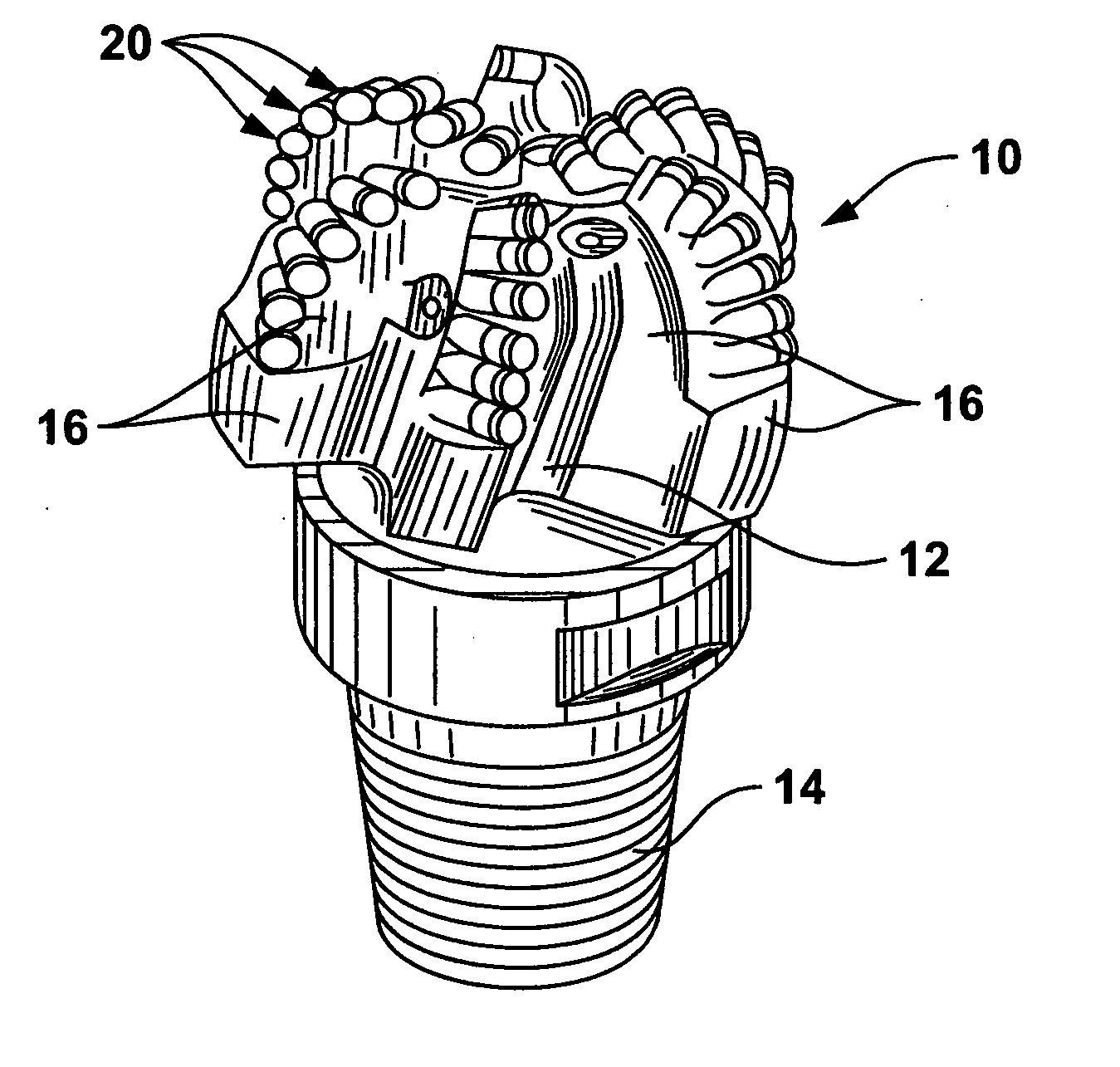
[0022] The present invention provides a braze alloy that includes one or more alloying elements to reduce braze temperature. In one or more embodiments, the alloying elements may also increase braze strength. Braze alloys in accordance with one or more embodiments of the invention may be used in drilling tool applications, such as for brazing cutting elements in a drilling tool, as described below.
[0023] In one embodiment, a method for brazing a cutting element to a drill bit includes placing braze alloy into a cavity of a cutting element support structure of the drill bit. The braze alloy includes about 0.5% to about 10% by weight of at least one selected from the group of gallium (Ga), indium (In), thallium (Tl). The method also includes inserting at least a portion the cutting element into the cavity. The method further includes heating the braze alloy such that it melts between the cutting element and the cavity, and cooling the braze alloy to form a bond between the cutting el...
PUM
| Property | Measurement | Unit |
|---|---|---|
| Fraction | aaaaa | aaaaa |
| Fraction | aaaaa | aaaaa |
| Fraction | aaaaa | aaaaa |
Abstract
Description
Claims
Application Information