[0010] Alternatively, the invention provides a method of reducing
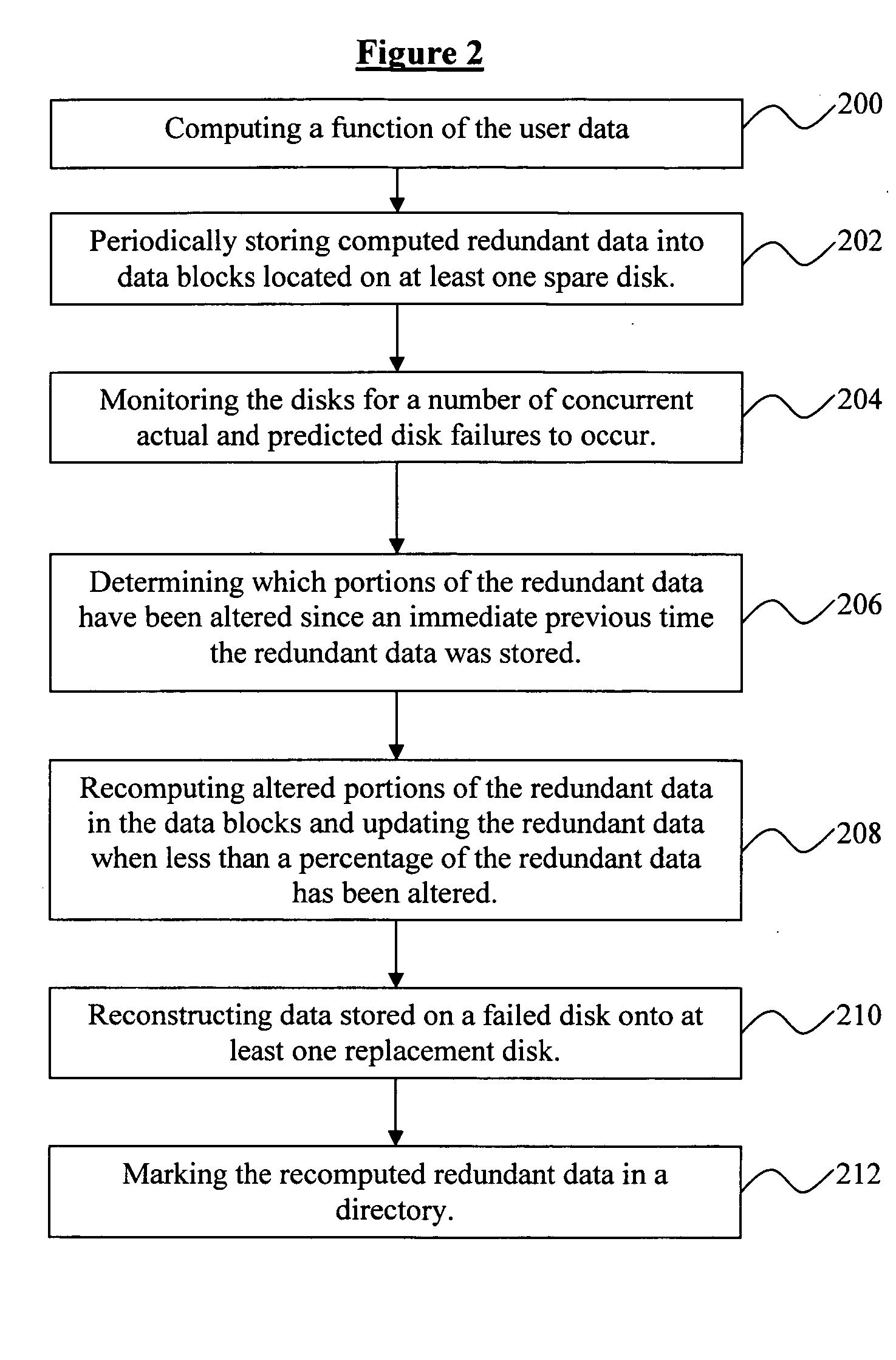
data loss in a disk array comprising periodically storing redundant data into data blocks located on a disk, monitoring the disks in the disk array for a number of disk failures to occur, determining which of the data blocks contain redundant data that has been altered since an immediate previous time the redundant data was stored, recomputing altered portions of the redundant data, and storing the recomputed altered portions in the data blocks, wherein the number of disk failures include disk failures that are predicted to occur. The method further comprises updating the data blocks comprising altered redundant data when the number of disk failures have occurred, and reconstructing data stored on a failed disk onto at least one replacement disk. Moreover, the disk array comprises at least one a
RAID array. The step of updating the data blocks comprising altered redundant data is skipped if a number of the data blocks exceeds a fraction of the data stored in the disk array. Additionally, the redundant data is stored on at least one spare disk, and the data blocks containing altered redundant data are updated whenever the load on the disk array is below a threshold value. Furthermore, the data blocks containing altered redundant data that is less likely to be altered again are preferentially updated.
[0011] In another embodiment, the invention provides a
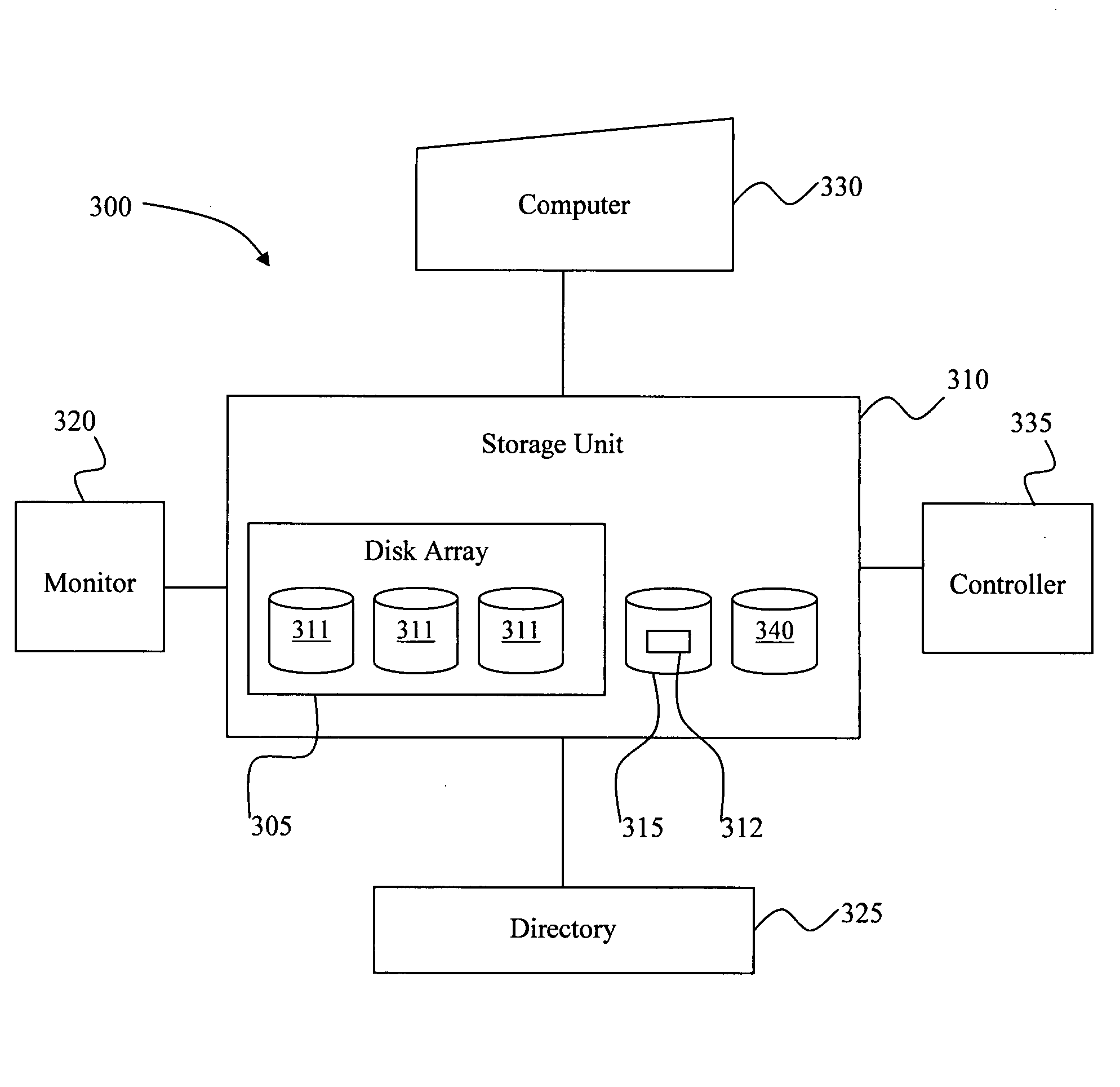
system for reducing data loss in a disk array comprising a storage unit operable for periodically storing redundant data into data blocks located on a disk, a monitor operable for monitoring the disks in the array for a number of disk failures to occur, a
directory operable for determining which of the data blocks contain redundant data that has been altered since an immediate previous time the redundant data was stored, and a computer operable for computing redundant data of the data stored in the disk array and for recomputing altered portions of the redundant data, wherein the number of disk failures monitored include disk failures that are predicted to occur. The
system further comprises a controller operable for updating the redundant data when the number of disk failures have occurred, at least one replacement disk operable for storing reconstructed data previously stored on a failed disk, and at least one spare disk operable for storing the redundant data, wherein the
directory is operable for marking the recomputed redundant data in the directory. Moreover, the disk array comprises at least one a
RAID array. The system further comprises a controller operable for updating the redundant data whenever the load on the disk array is below a threshold value, wherein the controller preferentially updates redundant data that is less likely to be altered again.
[0012] The advantages of the invention are numerous. Currently, to increase the number of disk failures that a disk array can tolerate without losing user data, it is necessary to use more
disk space to store more redundant data, and more importantly, the additional redundant data would have to be computed and updated every time the user data is written. This is very costly (e.g., multiple reads and multiple writes). Therefore, most systems tolerate only a single disk failure. However, multi-disk failures are increasing and they are costly. In one aspect, the invention makes it possible to achieve higher levels of
fault tolerance without incurring significant extra
disk space and operations to maintain the redundant data. In another aspect, the invention reduces the time and
data processing needed to re-achieve desired levels of
data redundancy after one or more disks in a disk array has failed in order to reduce the chance and amount of data loss.
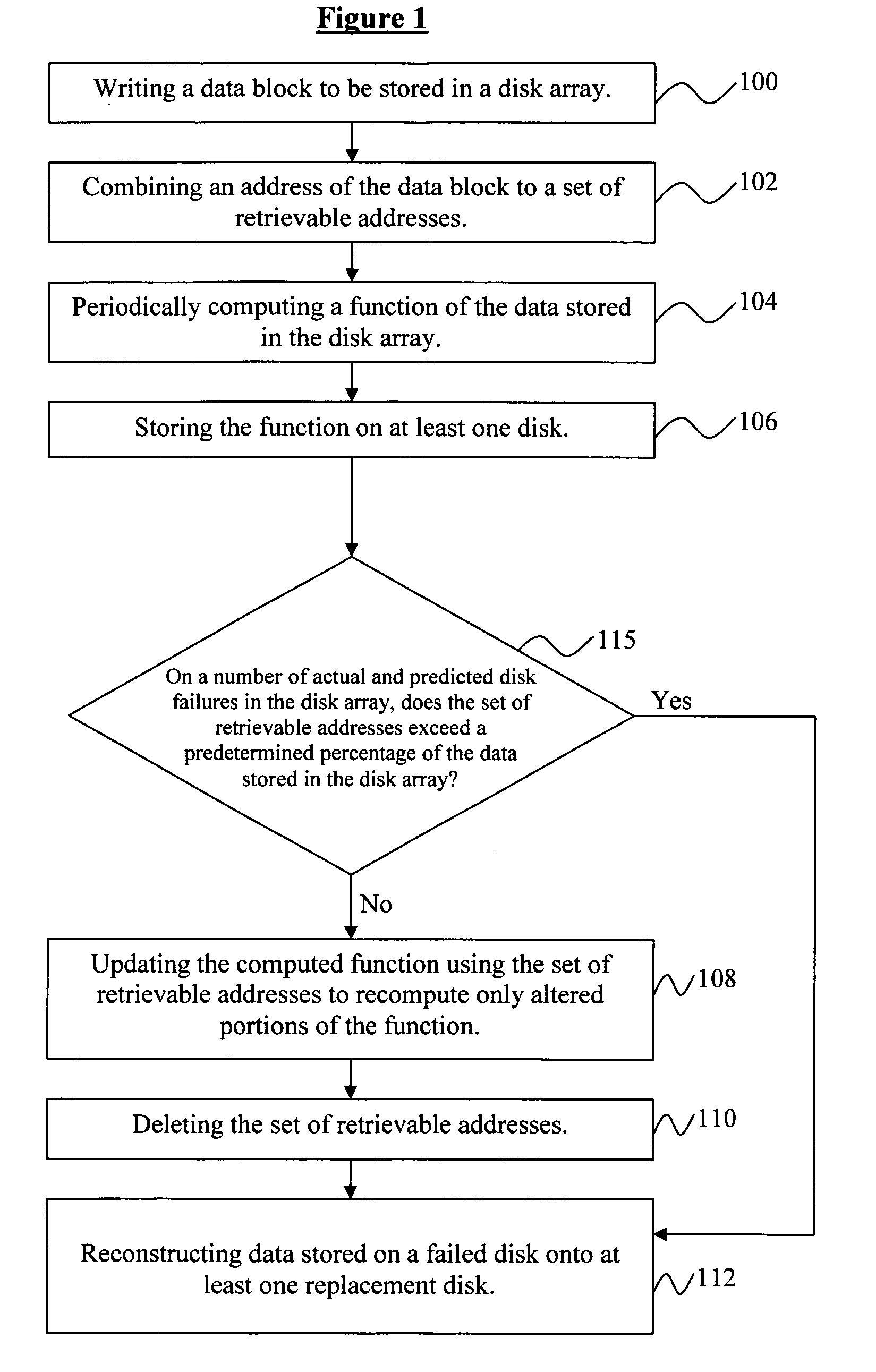
[0013] In order to achieve this, the invention periodically computes redundant data and stores the computed data preferably on the spare disks in the system. Then when needed (
on demand) such as when disks fail or are predicted to fail, the invention updates the redundant data by recomputing and writing only the parts that have changed. Predicted disk failures are disk failures that are believed likely to occur within a time interval. Methods of predicting disk failures are known in the art [6]. Since the amount of user data that is updated tends to be very small, on the order of a few percent (<5%) per day [3], this, in effect, dramatically decreases the time needed to re-achieve
data redundancy. Compared to a traditional system that always keeps all the redundant data updated, the invention, in contrast, provides performance in which much fewer operations are performed since many blocks containing user data are written more than once (the write traffic is much higher than the write
working set). Moreover, the invention allows the system to defer most of the operations for updating the redundant data to a more convenient time so that there is dramatically less
impact on foreground performance.
[0014] Currently, most of the data loss situations in the widely-used RAID-5 array [1] result (1) when there is more than one concurrent disk failure, and (2) when there is one disk failure followed by a subsequent failed sector read on another disk during the rebuild process to recover the user data that was on the failed disk. The invention makes it unnecessary to read most (>95%) of the user data to re-achieve
data redundancy after a disk failure in the RAID-5 array. It therefore dramatically reduces the second type of data loss situations. By greatly reducing the amount of data that has to be processed to re-achieve data redundancy, the invention also re-establishes data redundancy much quicker so that the first type of data loss situations is much less likely to occur.

