Internal combustion engine with oil temperature sensor

a technology of oil temperature sensor and combustion engine, which is applied in the direction of machines/engines, mechanical equipment, crankcase compression engine lubrication, etc., can solve the problem of possibly restricted layout of temperature sensor, and achieve the effect of reducing the influence of thermal radiation from the exhaust pip

Inactive Publication Date: 2005-05-05
HONDA MOTOR CO LTD
View PDF4 Cites 19 Cited by
  • Summary
  • Abstract
  • Description
  • Claims
  • Application Information

AI Technical Summary

Benefits of technology

[0017] According to the above-described embodiment of the invention, there is no possibility that on the exposure portion of the driving state sensor installed to the engine body, radiant heat from the exhaust pipe directly strikes by the engine body. The radiant heat from the portion facing the engine body, which is particularly a portion of the exhaust pipe to be arranged comparatively close to the driving state sensor, is shielded by the engine body itself without providing the engine body with ribs and the bracket, and yet without the need for arranging the exhaust pipe far apart from the exposure portion because the portion which those face is arranged facing the other side portion of the engine body different from one side portion in which the exposure portion is arranged. As such, the oil temperature sensor is capable of detecting accurate temperature with the influence of thermal radiation from the exhaust pipe reduced.

Problems solved by technology

For this reason, there is a drawback that the cylinder block becomes large-sized by a portion corresponding to the oil return passage to be formed, and further the temperature sensor is to be arranged so as to avoid the timing chain chamber having comparatively large width in the circumferential direction with the cylinder axis as the center while excluding interference with and influence of peripheral members to be arranged around the cylinder block such as exhaust pipes.
Therefore, layout of the temperature sensor has possibly been restricted.

Method used


Image

  • Internal combustion engine with oil temperature sensor
  • Internal combustion engine with oil temperature sensor
  • Internal combustion engine with oil temperature sensor

Examples


Embodiment Construction

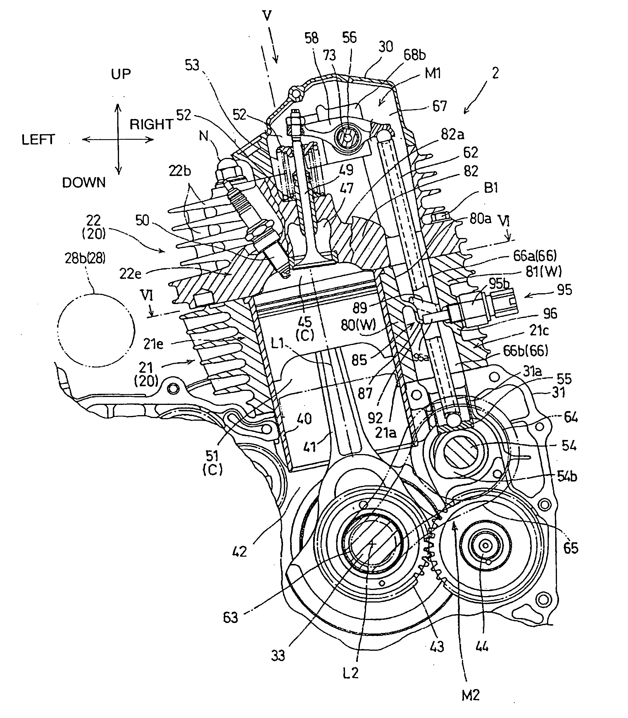
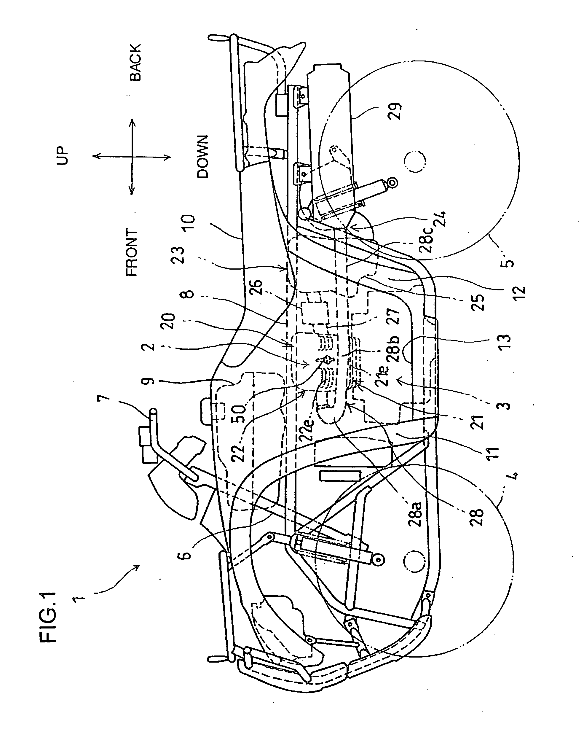
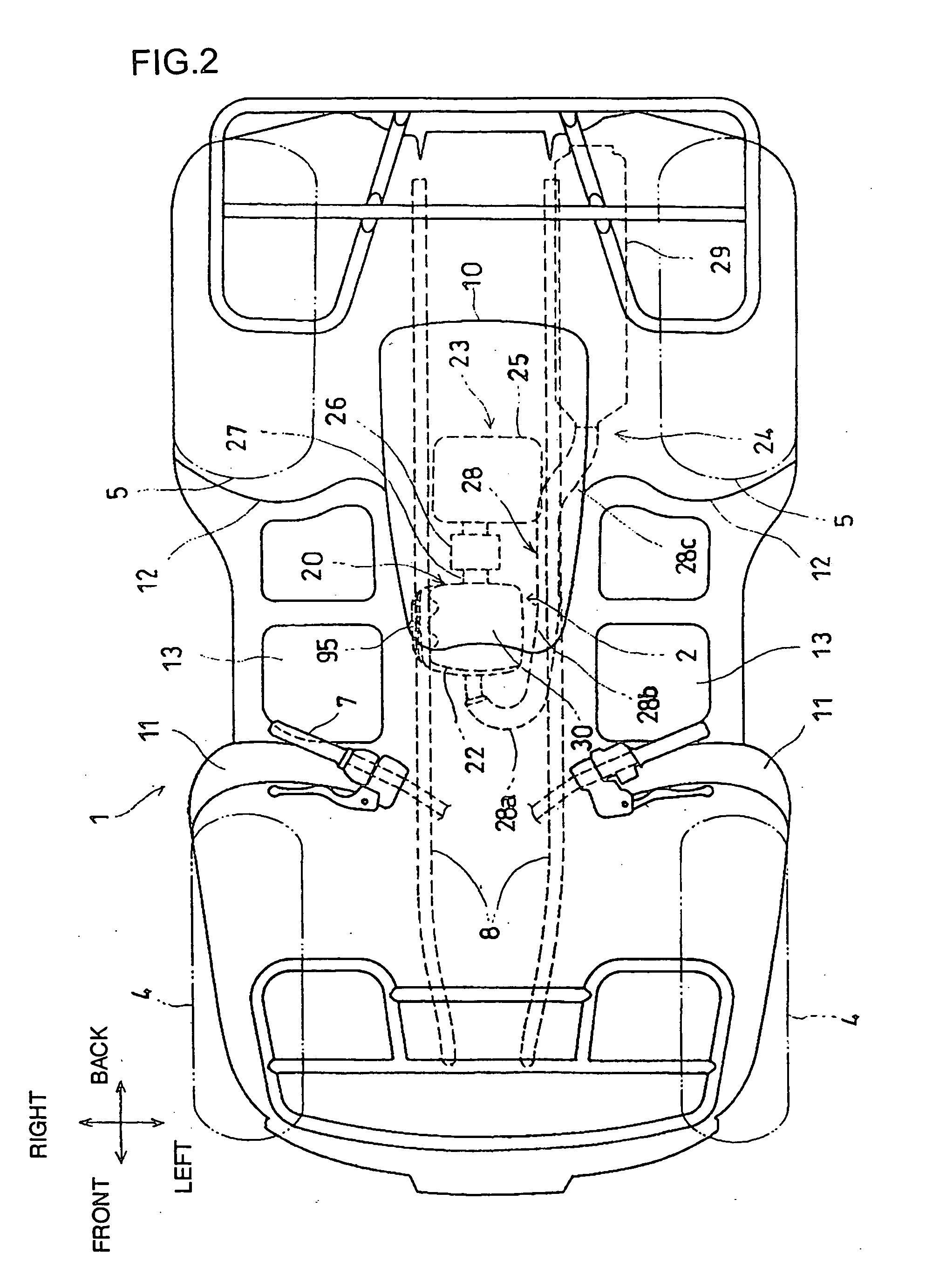
[0025] Hereinafter, with reference to FIGS. 1 to 7, the description will be made of an embodiment of the present invention.

[0026] Referring to FIGS. 1 and 2, an internal combustion engine 2 to which the present invention has been applied, is mounted on a saddle-ride type vehicle 1 capable of traveling on a uneven land. In a body frame of the vehicle 1, in the front portion thereof, there are installed a pair of left and right front wheels 4, in the rear portion thereof, a pair of left and right rear wheels 5, and in the intermediate portion thereof, a power unit composed of an internal combustion engine 2 and a transmission 3 respectively. Both front wheels 4 are steered by a handlebar 7 installed to the upper end portion of the handlebar post 6 via an interlocking mechanism (not shown) to be provided on the lower end portion side of the handlebar post 6. Also, the vehicle 1 is a four-wheel-drive vehicle, and both front wheels 4 and both rear wheels 5 are driven by a driving shaft ...


PUM


Abstract

The invention relates to an engine arrangement that increases the degree of freedom of the engine state sensor while decreasing the size of the engine body. More specifically, the engine is formed with a chamber for housing a valve train and serving dually as a return oil path of the lubricating oil after having lubricated the valve train. The engine includes an oil temperature sensor partially exposed on one side of a cylinder block and an exhaust pipe partially exposed on the opposite side of the cylinder block.

Description

CROSS REFERENCE TO RELATED APPLICATIONS [0001] This application is based on Japanese patent application nos. 2003-327624 and 2003-327625. FIELD OF THE INVENTION [0002] The present invention relates to an internal combustion engine with a sensor for detecting the running state of the engine. BACKGROUND OF THE INVENTION [0003] Oil temperature sensors for detecting temperature of lubricating oil in an internal combustion engine are conventionally used to detect temperature of lubricating oil within a lubricating oil passage or within an oil pan. For example, in an internal combustion engine disclosed in Japanese Patent No. 2000-213326, an oil return passage for returning the oil which has lubricated a valve train is formed by penetrating a cylinder block. An intermediate portion of the oil return passage bulges downward forming an oil reservoir and a detection unit of a temperature sensor which has been threadedly inserted from a side wall of the cylinder block faces the oil reservoir....

Claims


Application Information

Patent Timeline
Patent Type & Authority Applications(United States)
IPC IPC(8): F01N13/10F01M11/02F01N13/08F02B77/08F02F1/24
CPCF01M2011/023F01N13/08F02F1/24F02B77/089F01N2590/04
Inventor EGUCHI, MASATAKANARITA, SATORUADACHI, MASAYAURABE, MASANOBU
Owner HONDA MOTOR CO LTD
Why Eureka
Try Eureka