
Spider Jet for Intake Manifolds

Inactive Publication Date: 2005-05-05
PARKS BARRON
View PDF6 Cites 0 Cited by
  • Summary
  • Abstract
  • Description
  • Claims
  • Application Information

AI Technical Summary

Benefits of technology

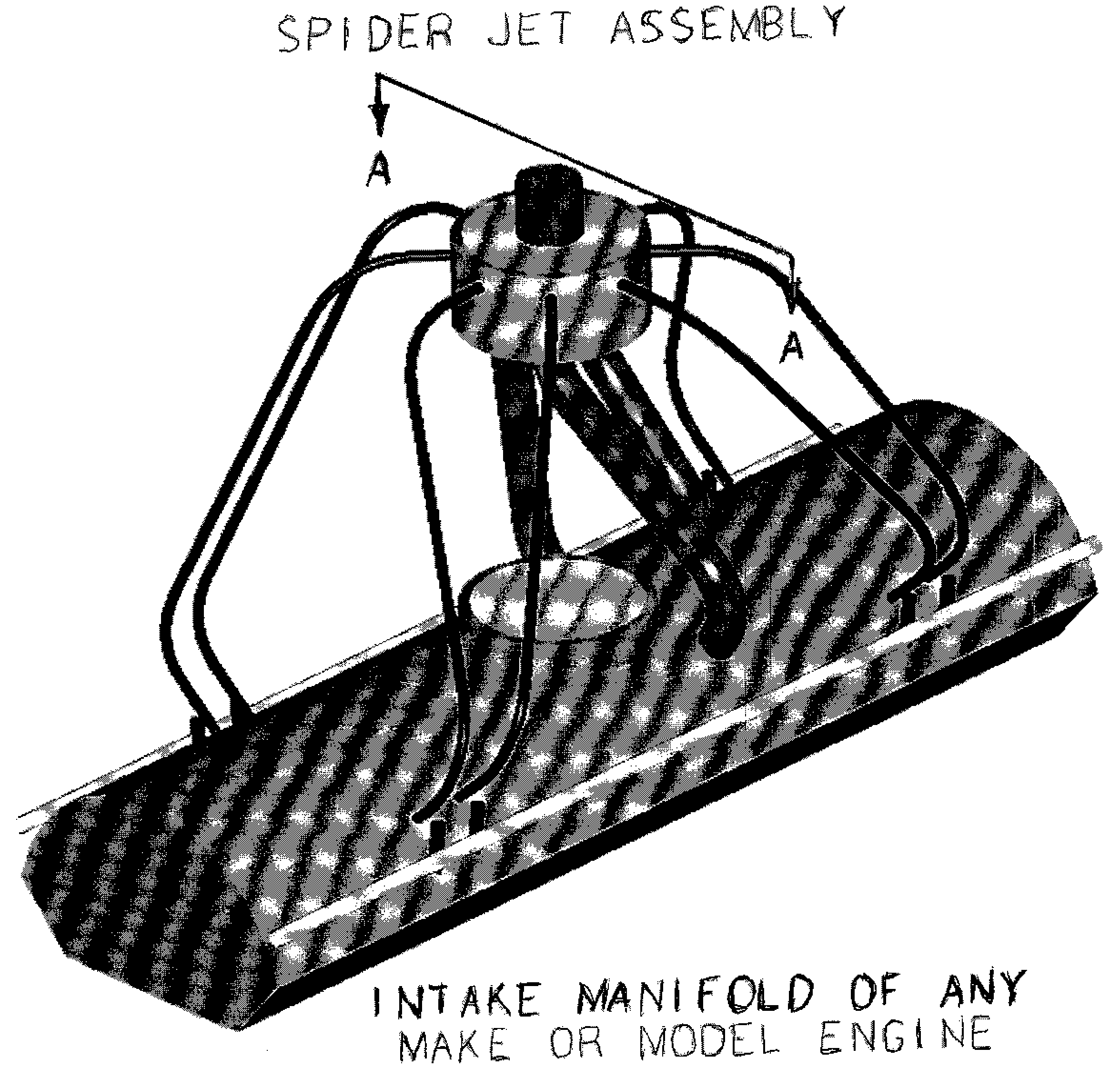
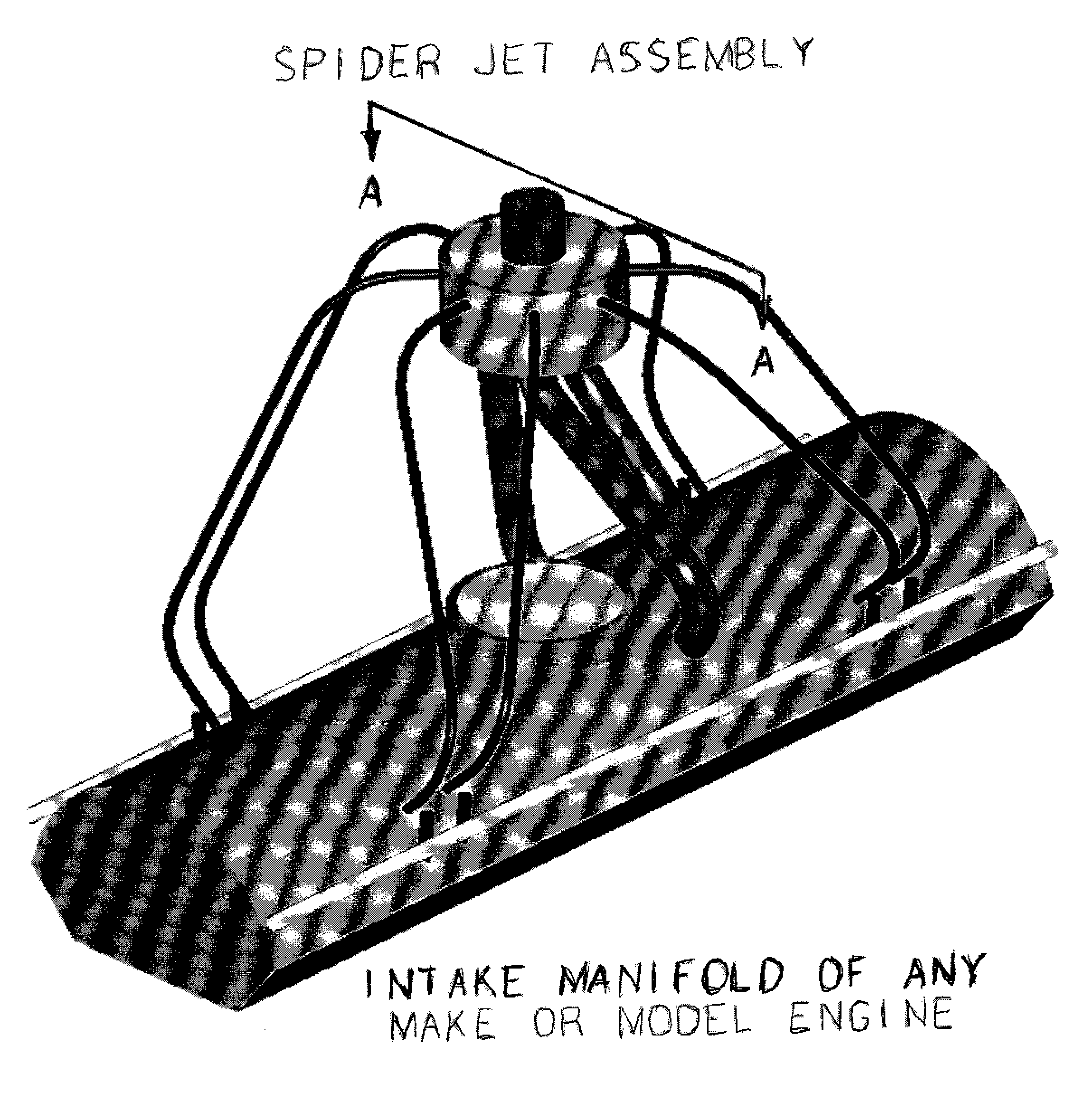
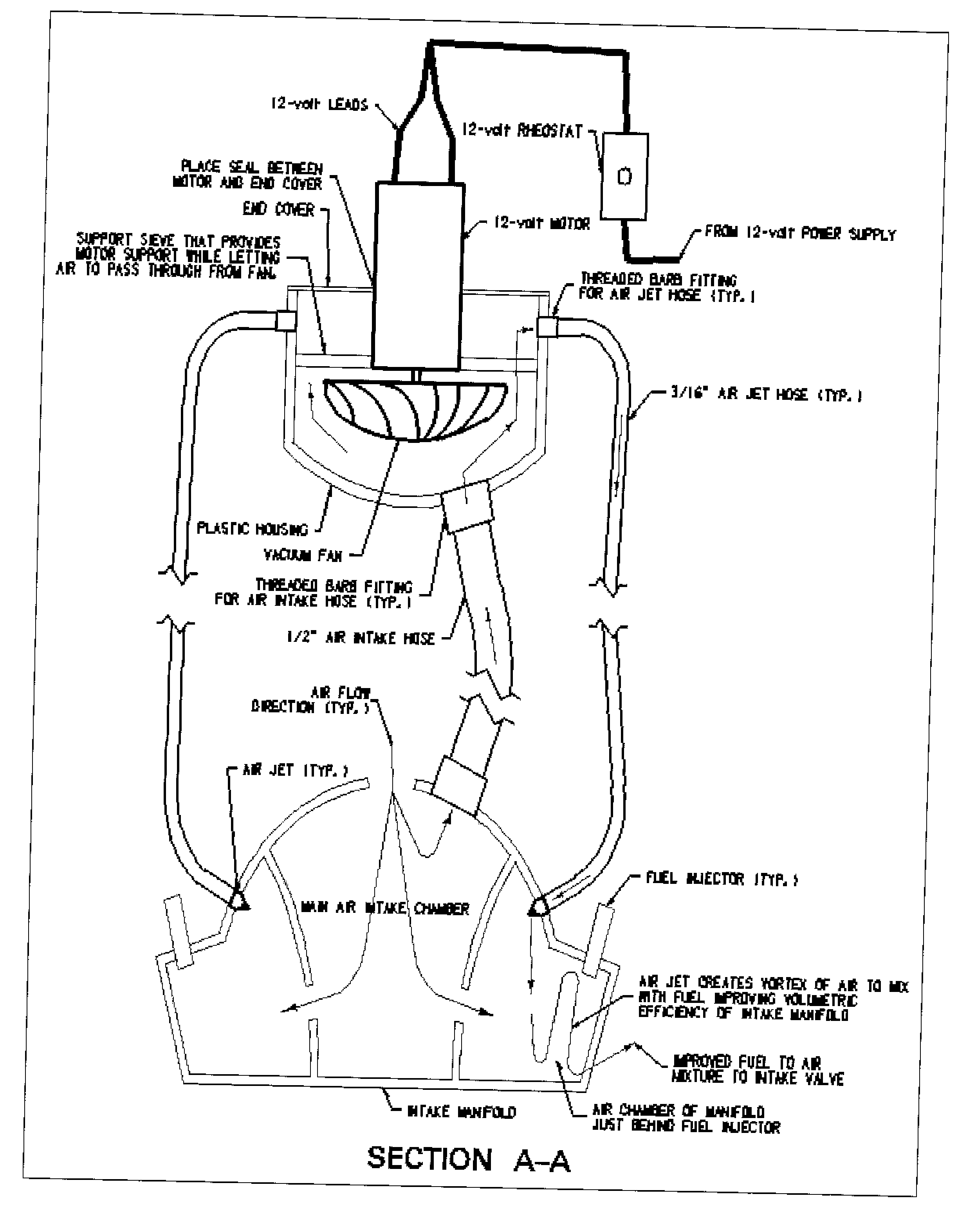
[0002] The Spider Jet is a vacuum device that pulls air or the air-fuel mixture from the main intake chamber of the intake manifold and delivers it more efficiently to the intake valve. The main intake chamber is directly under the throttle body or carburetor assembly depending on what type of fuel system is in use. The Spider Jet then redirects and compresses the air into smaller hoses. The air or air-fuel mixture is then forced back into the intake manifold above the intake valve through an air jet. The forced air then creates a vortex of air and / or air-fuel at the intake valve and thus provides the fuel and air additional mixing time. In carbureted engines, the Spider jet equalizes the fuel distribution to the cylinders located furthest from the carburetor and in fuel-injection systems, the Spider jet improves the volumetric efficiency of the intake manifold.

Problems solved by technology

The one overriding problem with the carbureted fuel intake system was its inability to equally disperse fuel to all the cylinders of the engine.
But all the development has over-looked one major problem, the fuel efficiency of the intake manifold.
So the problems of both types of fuel delivery are apparent.
The newer fuel-injected engines do not allow the fuel and air enough time to mix properly and thus have reduced efficiency but because a large amount of fuel is injected into the cylinders, the engines deliver consistent and increased horsepower.

Method used


Image

  • Spider Jet for Intake Manifolds
  • Spider Jet for Intake Manifolds
  • Spider Jet for Intake Manifolds

Examples


Embodiment Construction

[0005] The Spider Jet device solves the weak horsepower problem of older carbureted engines and the poor fuel efficiency problems of the modern fuel-rail and injectors delivery system. It does this by equally distributing fuel and air to all cylinders in the older engines and by improving the volumetric efficiency in the newer models intake manifolds. The device is constructed using a simple 12-volt vacuum device. These can be purchased as a 12-volt hand held vacuum cleaner usually advertised as car vacuums that can plug into the cigarette lighter outlet in the passenger compartment of automobiles. Once purchased the motor, vacuum fan, and cord can be easily disassembled from the proprietary housing. A 3-inch poly-vinyl chloride (PVC) end cap or similar sized plastic housing that will accommodate the vacuum fan is used to provide the main body of the device. Depending on the size of the engine, the size of the vacuum fan, intake hoses, jet hoses, and air jets may need to be larger o...


PUM


Abstract

The Spider Jet is an air redistribution system that can be fit on the intake manifold on any internal combustion engine. The Spider Jet is unique because it does not force additional air into the manifold, but rather redistributes the air already in the manifold to a more strategic location, which creates a better fuel to air mixture for the engine to consume. The better fuel to air mixture improves the horsepower of the engine, but also greatly improves the fuel efficiency of the engine.

Description

BACKGROUND OF INVENTION [0001] The Spider Jet was developed for use in the automotive industry. More specifically, to improve the volumetric efficiency of intake manifolds on the internal combustion engine. To understand the background of this invention, one must understand the reasons for the development of the modern fuel-injection system. For many decades the internal combustion engine was fed its fuel and air mixture by first, mixing the two components in a carburetion device and then distributing the mixture to the individual cylinders through an intake manifold. There were many adaptations and devices constructed to try and improve the horsepower and efficiency of this system. The one overriding problem with the carbureted fuel intake system was its inability to equally disperse fuel to all the cylinders of the engine. The development of the fuel rail and fuel injection system solved this problem. With this system, a fuel injector is placed near each intake valve and each cyli...

Claims


Application Information

Patent Timeline
IPC IPC(8): F02B29/00F02B33/32F02M23/00
CPCF02B29/00Y02T10/146F02M23/00F02B33/32Y02T10/12
Inventor PARKS, BARRON
Owner PARKS BARRON
Learn More