Folded tube for a heat exchanger and method of making same

Inactive Publication Date: 2005-05-05
VALEO INC
3 Cites 48 Cited by

AI-Extracted Technical Summary

Problems solved by technology

However, these sort of extruded tubes have the disadvantages of requiring internal dimensions that must have wide tolerances, in order to keep the extrusion dies life span at a reasonable level to be practical, i.e. tighter tolerances generally reduce die life, whereas the requirement of wider tolerances of most extruded tubes of this nature means that there is increased material usage, and, the extruded tubes, therefore, are relatively expensive to produce.
However, in those ‘solutions’ several other problems have been discovered: tube gauge might be not optimiz...

Benefits of technology

[0020] One advantage of the present invention is that a multi-port folded tube for a heat exchanger with such a locking feature can be used on with a variety of heat exchangers. In the case such as a condenser is provided for an air conditioning system of a motor vehicle for condensing liquid refrigerant. Another advantage of the present invention is that the folded tube is stamped and folded and is more economical to manufacture than an extruded tube. Yet another advantage of the present invention is that the folded tube has half webs that do not extend the entire height of the ports to be formed, and, therefore, do not require compression to make a folded top or folded bottom tube portion alone that has to extend to the opposing top or bottom tube portion respectively. Still another advantage of the present invention is that a method of making the folded tube is provided whereby various tube-end locking features may be utilized. Yet a further advantage of the present invention, particularly in pr...

Abstract

The present invention relates to a multi-port folded tube for a heat exchanger, and, in particular, a multi-port condenser tube and a method of making thereof. The present invention further comprises a folded tube and method of making a multi-port folded tube for a heat exchanger wherein at least one tube locking feature is included.

Application Domain

Technology Topic

EngineeringPlate heat exchanger +1

Image

  • Folded tube for a heat exchanger and method of making same
  • Folded tube for a heat exchanger and method of making same
  • Folded tube for a heat exchanger and method of making same

Examples

  • Experimental program(1)

Example

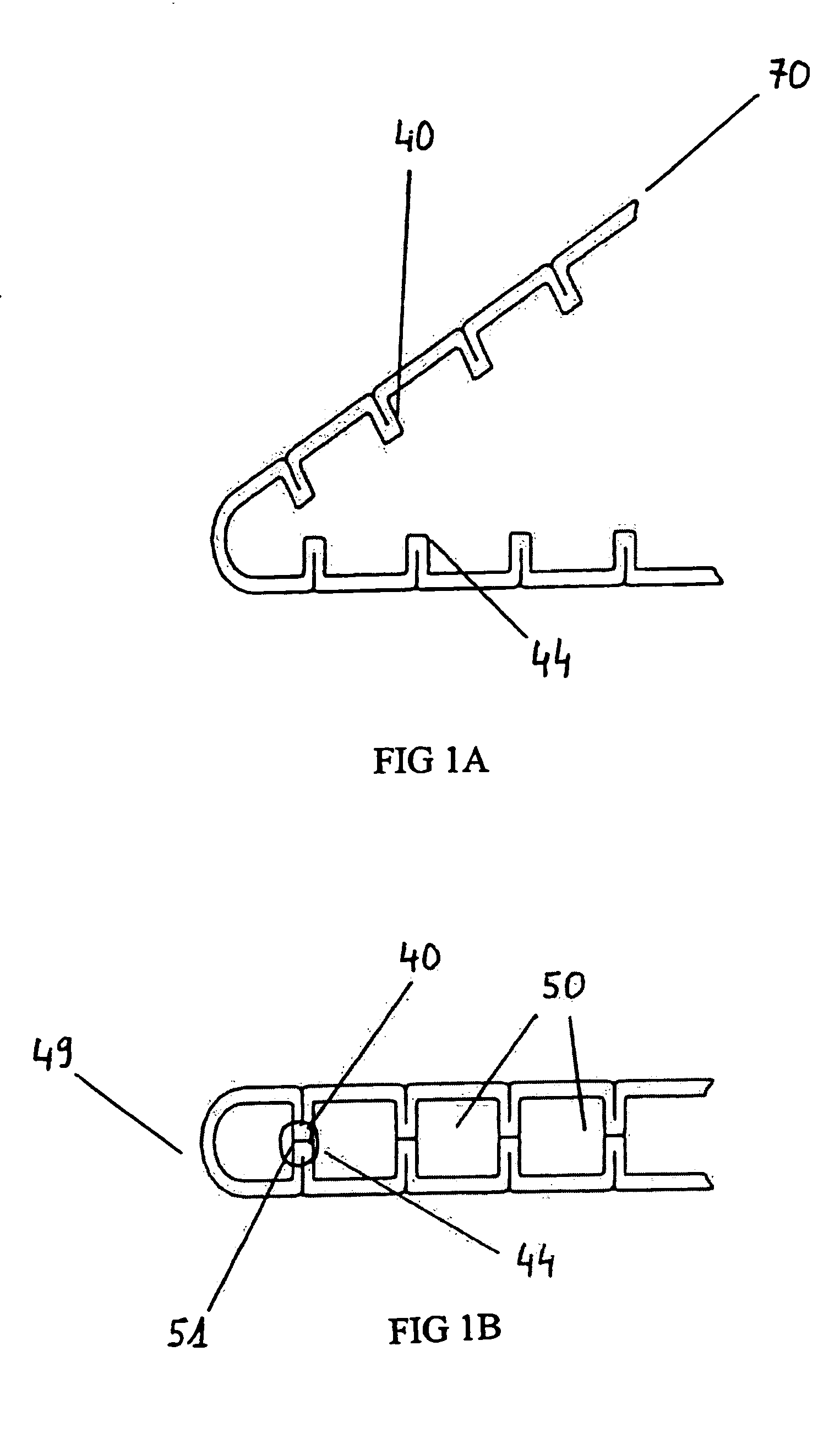
[0032] Referring to the drawings and particularly to FIG. 1a, 1b and FIG. 2 the basic process of tube folding in accordance with the present invention, and an embodiment of the subsequent tube 49 of the present invention is illustrated. A sheet material 70 is folded progressively into a muli-port 50 tube. The sheet 70 is folded to form several half-webs or internal half webs 40, 44, then bent into tube form. FIG. 1b shows the half web from the top surface 40 and the half webs from the base surface 44 face-to-face and abutting one another at point 51, together forming webs separating multi-ports.
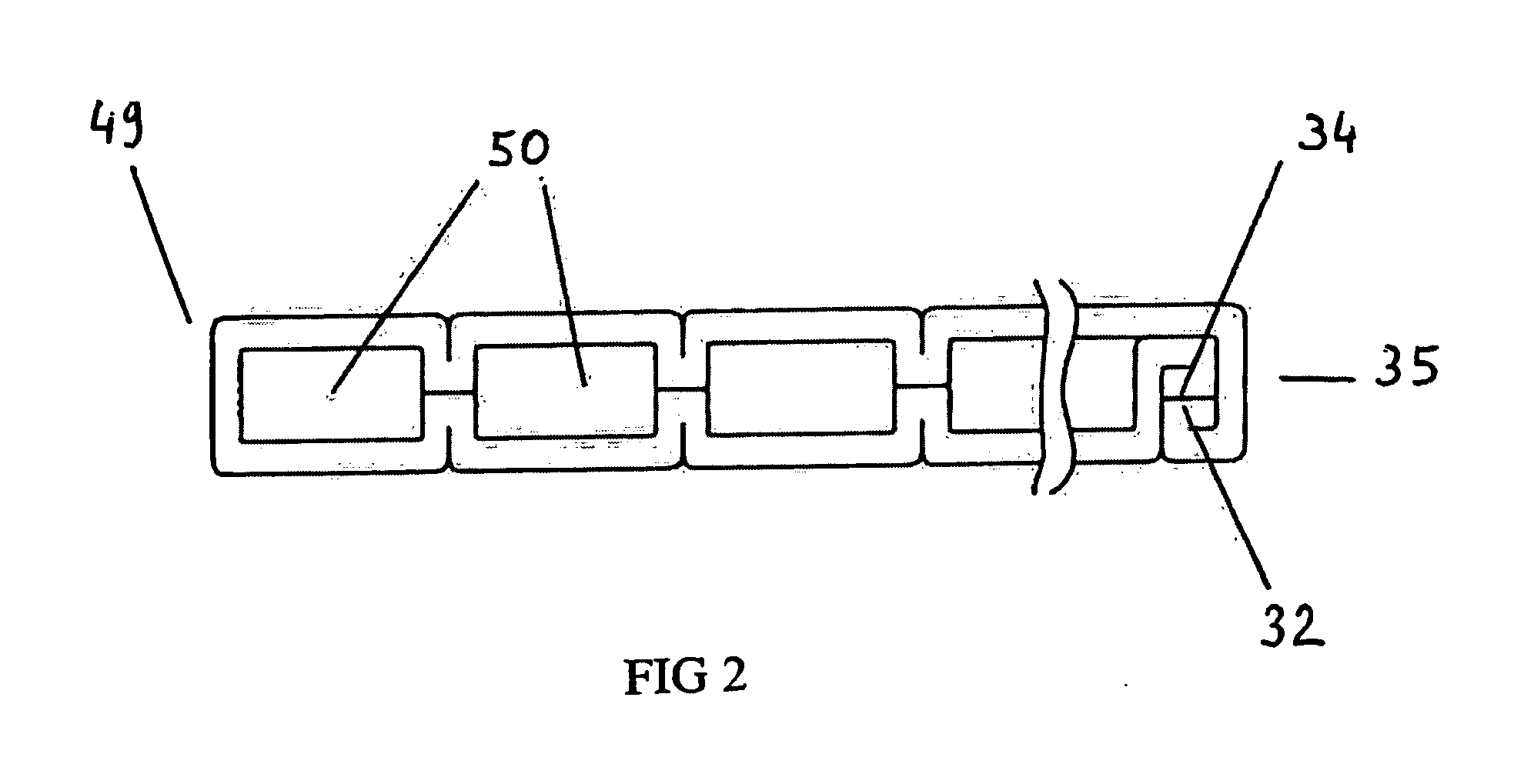
[0033] Referring to FIG. 2, at one end of the sheet ends 34 and 32, are bent twice inwardly on one end 34 yielding three layers and bent once on end 32 yielding 2 layers, together forming a 5-layer locked tube end 35, yielding specific relations between tube height and sheet gauge.
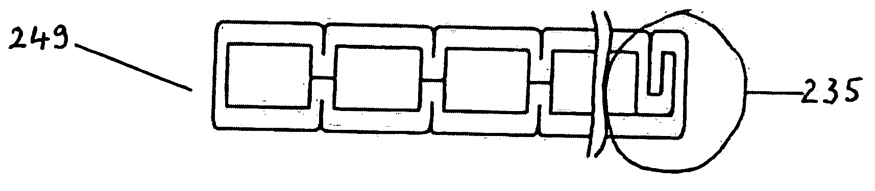
[0034] Referring to FIGS. 3a and 3b, the tube locking features 135,235 are formed. In FIG. 3a, one end 132 of the sheet is bent onto the other end 134 of the sheet 70. Subsequently end 132 and end 134 form locked end 135 that are bent to form the tube end 235 of FIG. 3b. The two locked sheet ends form another end of the multi-port tube. The end of the tube is formed by having one sheet end of sheet is bent onto the another sheet end, and then the both locked ends are bent to form a tube end.
[0035] Referring to FIG.4, the tube-locking feature 150 is not at tube end 350. Tube locking feature 150 is found, preferably, at the top of a middle port 351 of the folded tube 350.
[0036]FIG. 5 shows another preferred embodiment of the present invention. The tube-locking feature 250, as in FIG. 4, is not found at tube end. Preferably, the tube-locking feature 250 is found on the inside tubes 451 yielding a clearance between the two sheet ends (delta) which does not depend on the sheet width.
[0037] Referring to the drawings and in particular FIG. 6, one embodiment of a heat exchanger 10, according to the present invention, such as a condenser for an air conditioning system (not shown), is shown for a motor vehicle (not shown). The heat exchanger 10 includes a plurality of generally parallel folded tubes 49, according to the present invention, extending between oppositely disposed headers 14, 16. The heat exchanger 10 includes a fluid inlet 18 for conducting cooling fluid into the heat exchanger 10 formed in the header 14 and an outlet 20 for directing cooling fluid out the heat exchanger 10 formed in the header 16. The heat exchanger 10 also includes a plurality of convoluted or serpentine fins 22 attached to an exterior of each of the tubes 12. The fins 22 are disposed between each of the tubes 12. The fins 22 conduct heat away from the tubes 12 while providing additional surface area for convective heat transfer by air flowing over the heat exchanger 10. It should be appreciated that, except for the folded tube 12, the heat exchanger 10 is conventional and known in the art. It should also be appreciated that the folded tube 12 could be used for heat exchangers in other applications besides motor vehicles.
[0038] Referring to FIGS. 7a, 7b and 7c, and FIGS. 1 and 2, a method, according to the present invention, of the making the folded tube 49 is shown. The method includes the steps of providing a generally planar sheet 70 of elongate, deformable material coated with a braze material forming the base 24 and top 26 having their respective ends 32 and 34 edges along a longitudinal length thereof as illustrated in FIG. 7A. The ends 32 and 34 of the base 24 and top 26 can be either flat or arcuate as illustrated in FIGS. 1a, 2, 3a and 3b. Alternatively, for the folded tube 49, 249, 349 and 449, the ends can be formed as illustrated in FIGS. 3a through 5. The method includes the step of folding the sheet 70 from the lateral sides to initially form the internal half webs 40 on the top with the second internal half web 44 on the base to an initial predetermined web height and width as illustrated in FIG. 7B. The method also includes the step of aligning the internal half webs 40, 44 approximately face to face so that they may abut each other. The method includes the step of folding the ends 32 and 34 toward one another until they meet to form ports 50 as illustrated in FIGS. 1b and 2. The method includes the step of connecting the ends 32 and 34 together. The method includes the step of brazing the folded tube 49 by heating the folded tube 49 to a predetermined temperature to melt the brazing material to braze the ends 32 and 34 and the internal top half webs 40 to the base half webs 44. The folded tube 49 is then cooled to solidify the molten braze material to secure the ends 32 and 34 together and the internal top half webs 40 and the base half webs 44 together. It should be appreciated that, instead of the ends 32 and 34, the partition 150,250 of the folded tube 349,449 may be formed internally as in FIGS. 4 and 5. Accordingly, the folded tube is a cost reduction over current tubes. The folded tube has internal half webs that are folded and potentially ‘squeezed’ to maintain a predetermined distance between the top and base 24. The folded tube also has the internal half webs forming ports with a defined hydraulic diameter.
[0039] Preferred embodiments of the present invention, as described above, and in particular, as exemplified in FIG. 4, and 5 therefore result in use of less material for tube production, increased refrigerant cross sectional area availability, and, therefore, less internal pressure restriction for the air conditioning system. In one preferred embodiment of the present invention, the folded tube is a tube having a locking feature supported with a ‘T’ shaped wall 150 such that the end edges would be in the tube's interior side to maintain an approximately flat wall. In another preferred embodiment, the locking feature is contained within a ‘U’ shaped interior wall 451. Preferably, the ‘U’ shaped interior wall is ‘doubled’ such that the perpendicular end wall portions or edges would be between the tube's interior walls to maintain closed flat end wall. More preferred would be ‘U’ shaped walls wherein is doubled In a preferred method of the present invention, referring to FIG. 3a the planar sheet is shaped such that the width across the tube formed therefrom is greater than the height of the tube, and the edges of the planar sheet have a locking feature 135 In the form of a ‘J’.
[0040] The present invention has been described in an illustrative manner. It is to be understood that the terminology which has been used is intended to be in the nature of words of description rather than of limitation.
[0041] Many modifications and variations of the present invention are possible in light of the above teachings. Therefore, within the scope of the appended claims, the present invention may be practiced other than as specifically described.

PUM

no PUM

Description & Claims & Application Information

We can also present the details of the Description, Claims and Application information to help users get a comprehensive understanding of the technical details of the patent, such as background art, summary of invention, brief description of drawings, description of embodiments, and other original content. On the other hand, users can also determine the specific scope of protection of the technology through the list of claims; as well as understand the changes in the life cycle of the technology with the presentation of the patent timeline. Login to view more.

Similar technology patents

Folding Flue

Owner:OLYMPIA CHIMNEY SUPPLY

Spark plug with ceramic electrode tip

ActiveUS20150102721A1Economical to manufactureLong useful lifeSpark gapsSparking plugs manufactureElectrically conductiveEngineering
Owner:FEDERAL MOGUL IGNITION

Classification and recommendation of technical efficacy words

  • Economical to manufacture

Audio distribution and production system

InactiveUS20020177914A1Economical to manufactureEasy and flexible programmabilityBroadcast systems characterised by addressed receiversModulated-carrier systemsData fileSatellite
Owner:CHASE TIM
Why Eureka
Try Eureka