Barcode reader

a barcode reader and reader technology, applied in the field of barcode readers, can solve the problems of limiting the reciprocating range of scanning mirrors, consuming a lot of electric power, and improving the laser beam scanning unit, so as to promote reciprocation, improve accuracy, and reduce temperature dependence of eigen frequency f0

Inactive Publication Date: 2005-05-05
OLYMPUS CORP
View PDF7 Cites 7 Cited by
  • Summary
  • Abstract
  • Description
  • Claims
  • Application Information

AI Technical Summary

Benefits of technology

[0015] It is an object of the present invention to provide a barcode reader having a compact laser beam scanning unit, wherein metallic material is used for an elastic member which is supported by a support member, limits the range of reciprocating a scanning mirror to scan a laser beam, and promotes the reciprocation; the metallic elastic member and support member are molded as one body by insertion molding in the manufacturing process; different material is used for a support member and a scanning mirror which have different properties and characteristics; these support member and scanning mirror are molded as one body by injection molding; and the laser beam scanning unit is constructed with high accuracy, low temperature dependence of eigen frequency f0, and high durability against impact by dropping, while decreasing the accuracy requirement in the assembling process.

Problems solved by technology

This requires a motor driving system, and consumes much electric power.
Particularly, when considering a cordless unit, a problem arises in improvement of a laser beam scanning unit.
However, the laser beam scanning unit of the barcode reader disclosed in the Jpn. Pat. Appln. KOKAI Publication No. 2001-076085 uses one of resin, rubber and elastomer as an elastic member of a leaf spring, which limits the scanning mirror reciprocating range, and energizes the mirror in the direction to return essentially to the center position or to promote the reciprocation.
However, on the other hand, the eigen frequency f0 controls the laser scanning speed, and the temperature dependence of the eigen frequency is desirably low to obtain the stable barcode reading. performance always at every temperatures.
Further, the change of the scanning angle causes a change of the laser scanning angle, and affects the barcode reading performance.

Method used


Image

  • Barcode reader
  • Barcode reader
  • Barcode reader

Examples


Embodiment Construction

[0028] Hereinafter, embodiments of the present invention will be explained in detail.

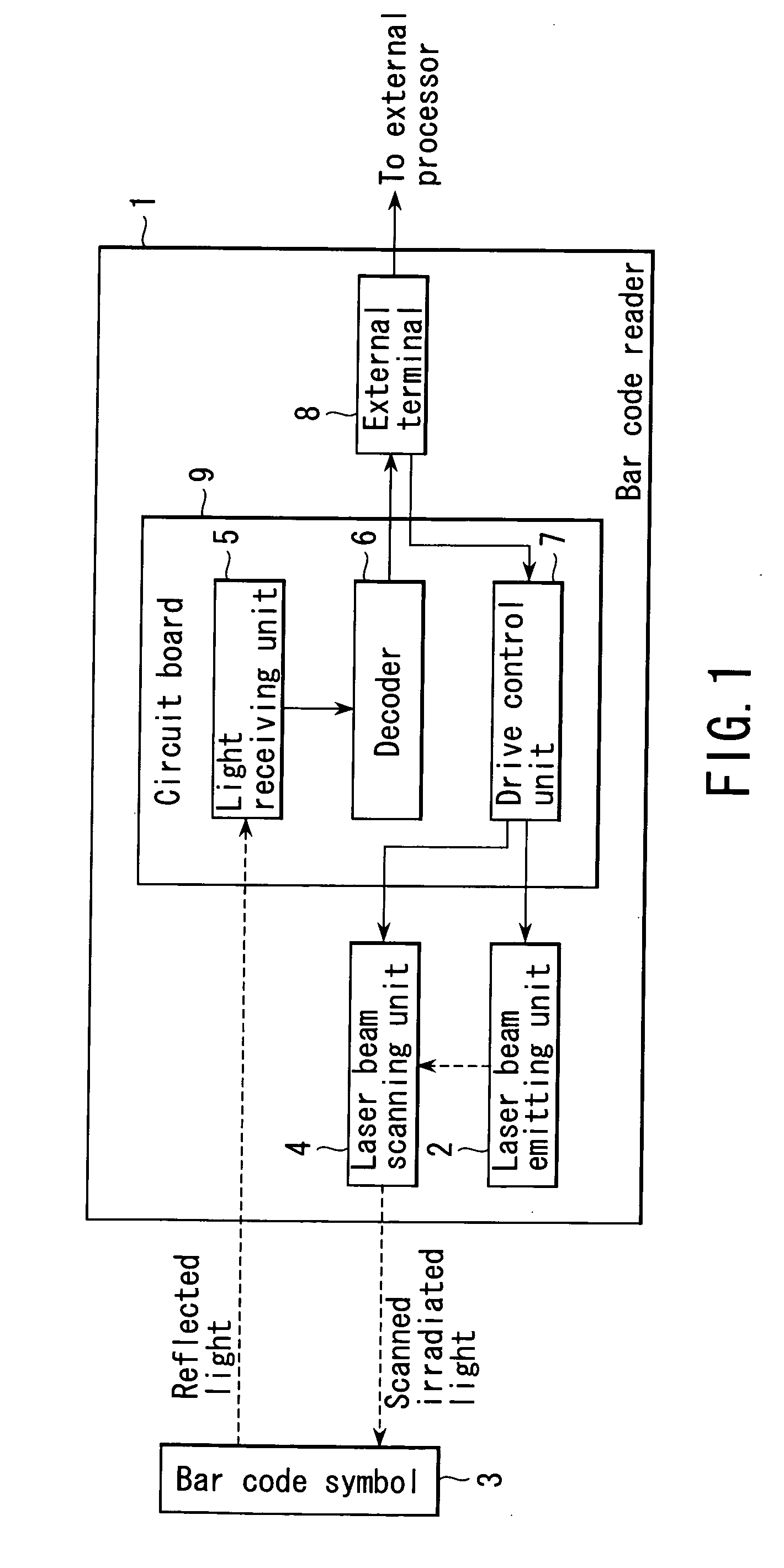
[0029]FIG. 1 shows the schematic configuration of a barcode reader according to a first embodiment of the present invention.

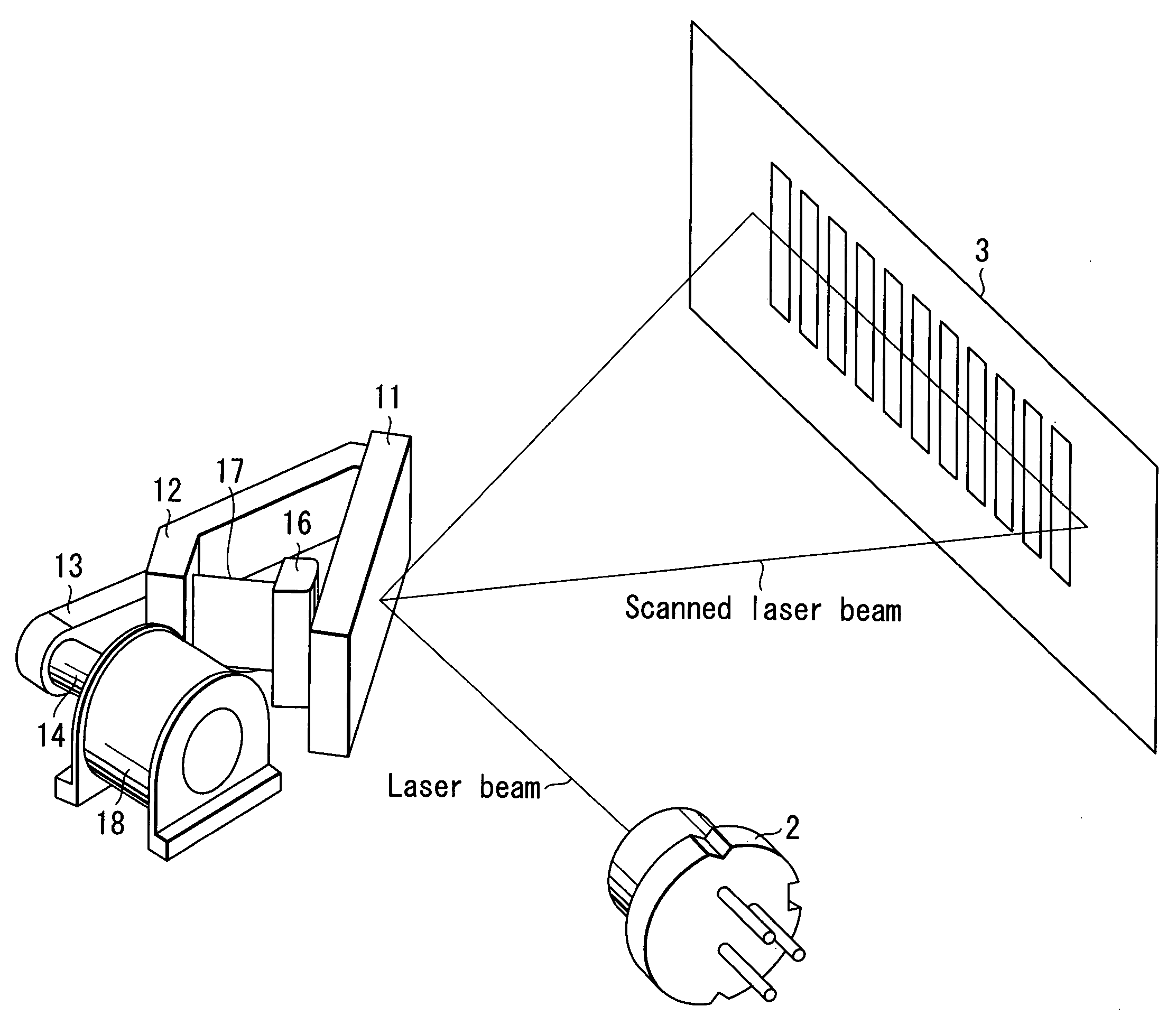
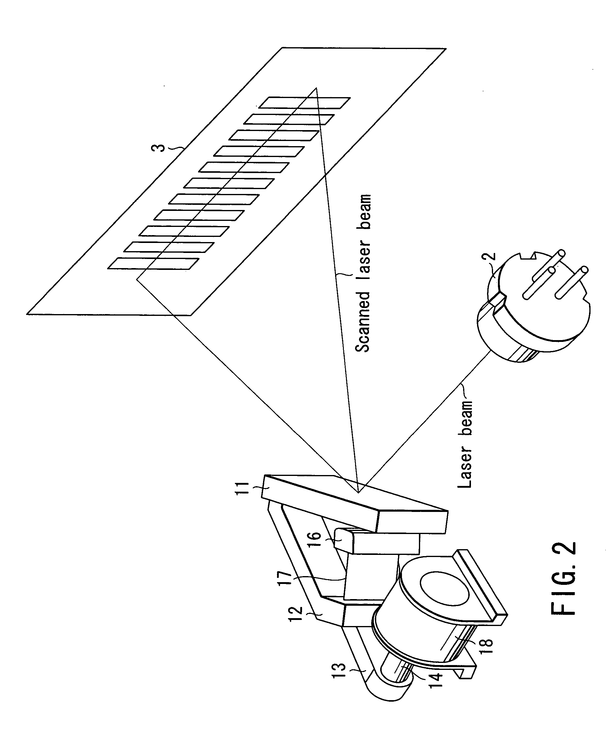
[0030] The barcode reader 1 comprises a laser beam emitting unit 2 which functions as a light source to emit a laser beam; a laser beam scanning unit 4 which scans the leaser beam emitted from the laser beam emitting unit 2, and irradiates it as a scanned laser beam toward a target barcode symbol 3; a light receiving unit 5 which takes in the light reflected from the barcode symbol 3, and generates a detection signal based on the intensity of the reflected light; a decoder 6 which processes the signal detected by the light receiving unit 5, and generates barcode information; and a drive control unit 7 which controls the driving of the laser beam emitting unit 2 and laser beam scanning unit 4. The barcode reader 1 also has an external terminal 8 for connection with a processor...


PUM


Abstract

The present invention provides a barcode reader, which irradiates a scanned laser beam onto a barcode symbol and reads the information written in the symbol, wherein a laser beam scanning unit is made by insertion molding as one body with a movable support member, a support member fixed to the main body, and a metallic elastic member connecting these support members, the support members are molded as one body with a scanning mirror, and a permanent magnet is fixed to the support members. A driving coil is provided in proximity to the permanent magnet, and generates an attractive force or a repulsive force to rotate the magnet at a periodic laser beam scanning angle. Further, a stopper mechanism is provided to soften an external impact to the rotation of the scanning mirror.

Description

CROSS-REFERENCE TO RELATED APPLICATIONS [0001] This is a Continuation Application of PCT Application No. PCT / JP03 / 05997, filed May 14, 2003, which was published under PCT Article 21(2) in Japanese. [0002] This application is based upon and claims the benefit of priority from prior Japanese Patent Application No. 2002-137875, filed May 14, 2002, the entire contents of which are incorporated herein by reference.BACKGROUND OF THE INVENTION [0003] 1. Field of the Invention [0004] The present invention relates to a barcode reader which scans and irradiates a laser beam from a scanning mirror onto a barcode symbol, and reads the written information from the reflected light, and more particularly to, improvement of a laser scanner which scans a laser beam. [0005] 2. Description of the Related Art [0006] Generally, a well-known barcode symbol consists of multiple bars of different line widths arranged with spaces to express various information according to the pattern of arrangement. Such a...

Claims


Application Information

Patent Timeline
Patent Type & Authority Applications(United States)
IPC IPC(8): G02B7/182G02B26/10G06K7/10
CPCG02B7/1821G06K7/10653G02B26/105
Inventor SHIMIZU, TOKUOKABEYA, AKIFUMI
Owner OLYMPUS CORP
Why Eureka
Try Eureka