
White light-emitting device

a light-emitting device and white light-emitting technology, which is applied in the direction of discharge tube luminescnet screens, energy-saving lighting, sustainable buildings, etc., can solve the problems of insatiable color rendering properties and reproducing ability, complicated design of driving circuits, and inability to uniformly produce white light in this way, etc., to achieve simple process, improve phosphor excitation efficiency, and process simple and stable

Inactive Publication Date: 2005-05-05
LITE ON TECH CORP
View PDF5 Cites 61 Cited by
  • Summary
  • Abstract
  • Description
  • Claims
  • Application Information

AI Technical Summary

Benefits of technology

[0012] It is the object of the present invention to provide a white light-emitting device having an LED and two phosphors excited by the LED. The white light-emitting device has simpler process in comparison with prior art.
[0016] In the white light-emitting device according to the present invention, only the blue or blue-green light-emitting diode consumes electrical power, therefore, the white light-emitting device can be operated with low current.
[0018] The white light-emitting device according to the present invention has following particular advantages:
[0019] 1. The short-wavelength (below 470 nm) blue LED has the drawback of manufacture. The white light-emitting device according to the present invention uses long wavelength blue or blue-green LED, which has simpler process. Moreover, the long wavelength blue or blue-green LED has better efficiency in phosphor excitation.
[0020] 2. In the present invention, the luminescent wavelength of phosphor is adjusted by modulating the crystal field of the host matrix of used phosphor instead of changing the amount of foreign ions. The process is simpler and more stable. The various objects and advantages of the present invention will be more readily understood from the following detailed description when read in conjunction with the appended drawing, in which:

Problems solved by technology

Moreover, the driving voltages for LEDs of different colors are also different; this complicates the design of driving circuit.
However, the white light produced in this way has no uniform spectral distribution (especially in 400 nm-700 nm) as the natural white light such as sunlight.
Therefore, the color rendering property and reproducing ability are not satisfactory and this white light source is used mainly for lighting.
The fourth prior art white light source has the drawbacks of low luminescent efficiency (only 8 lm / W) and short lifetime about 8000 hours.

Method used


Image

  • White light-emitting device
  • White light-emitting device
  • White light-emitting device

Examples


Embodiment Construction

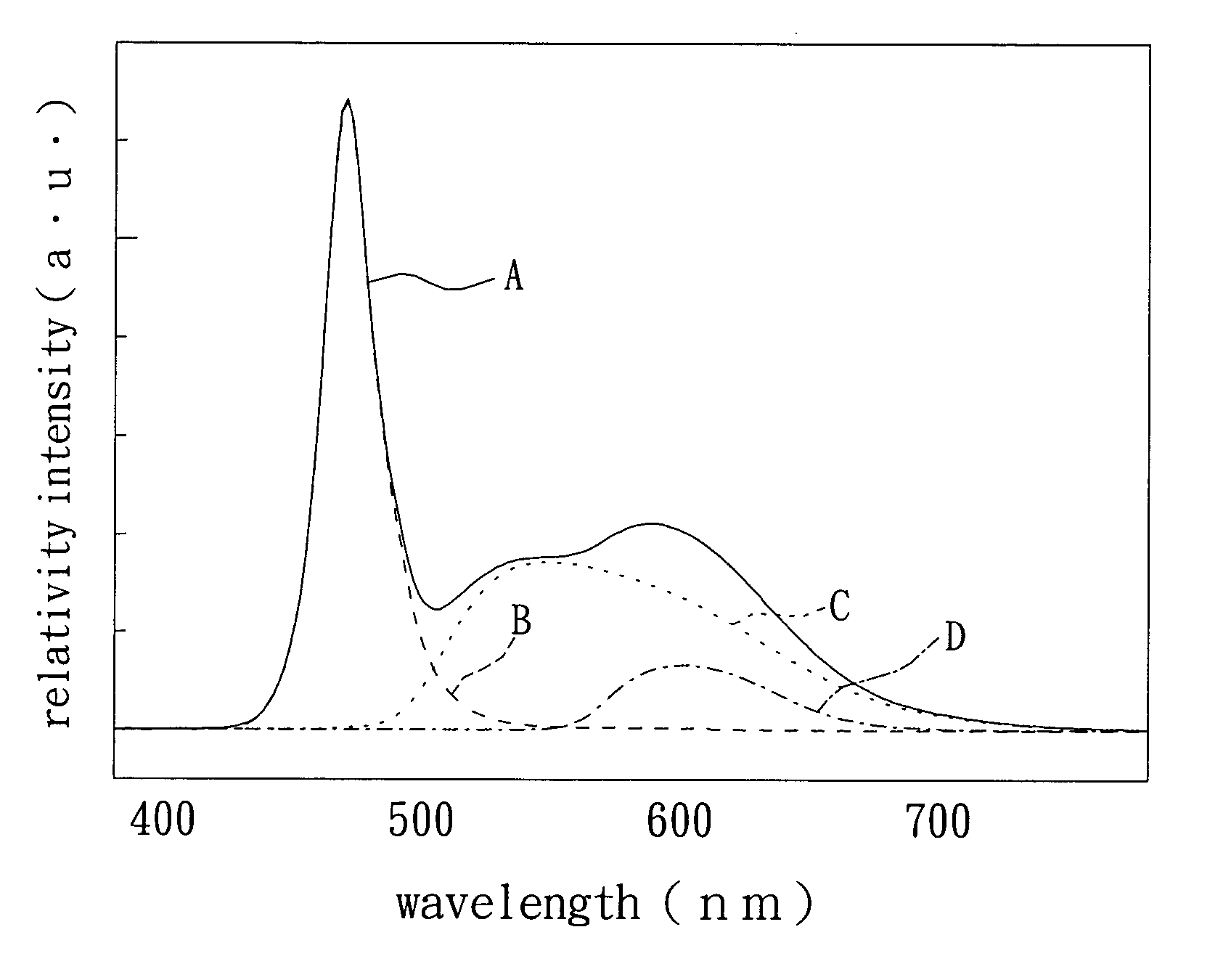
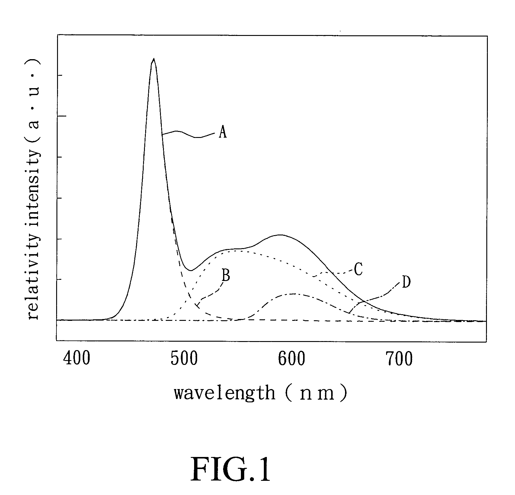
[0023] The present invention provide a white light-emitting device having an LED and two phosphors excited by the LED. The three colors generated by the LED and the two phosphors are mixed to provide a white light. The LED is a blue or a blue-green LED with emitting wavelength from 450 to 500 nm, preferably from 470 to 500 nm. The two phosphors include a yellow phosphor and a red phosphor to emit yellow radiation of 520-580 nm and red radiation of 580-640 nm. The yellow phosphor and the red phosphor can be mixed with a package material with different ratio to form a white light-emitting device with different color temperature and color rendering property.

[0024] The formula of the yellow phosphor is (YxMyCez)Al5O12, wherein x+y−3, and xy≠0, 0.5>z>0, M is selected from a group consisting of Tb, Lu and Yb, wherein (YxMyCez)Al5O12 is host matrix and Ce is luminescence center. The formula of the red phosphor is (M′aEub)S, wherein a+b=1˜1.2, and a, b≠0, M′ is selected from a group consis...


PUM

PropertyMeasurementUnit
wavelengthaaaaaaaaaa
operation voltageaaaaaaaaaa

Abstract

A white light-emitting device comprising a blue or blue-green light-emitting diode emitting light of 450-500 nm wavelength, and two phosphor materials capable of emitting a yellow light with 520 to 580 nm wavelength, and a red light with 580 to 640 nm wavelength, respectively. The light-emitting diode and the two phosphor materials are packaged together to form the white light-emitting device.

Description

FIELD OF THE INVENTION [0001] The present invention relates to a high-brightness white light-emitting device, especially to a high-brightness white light-emitting device with a blue or blue-green LED and two phosphors including a yellow phosphor and a red phosphor to emit yellow radiation and red radiation upon excitation. BACKGROUND OF THE INVENTION [0002] A white light source is generally provided by mixing light source of different wavelength. For example, a conventional white light source can be realized by mixing red light, green light and blue light with suitable intensity ratio. Alternatively, the white light source can be realized by mixing yellow light and blue light with suitable intensity ratio. The conventional method for manufacturing white light source can be summarized as following: [0003] In a first prior art of white light source, three LED dies based on AlInGaP, InGaN and Gap are packaged into a lamp and emit red light, blue light and green light, respectively. The...

Claims


Application Information

Patent Timeline
Patent Type & Authority Applications(United States)
IPC IPC(8): C09K11/77H01J1/62H01L33/50H05B33/00
CPCC09K11/7731C09K11/7774Y02B20/181H01L33/504H01L33/502Y02B20/00
Inventor WANG, CHIEN-YUANLIU, RU-SHISU, HUNG YUAN
Owner LITE ON TECH CORP
Learn More