Display panel, method of manufacturing display panel, and display apparatus

Active Publication Date: 2005-05-05
138 EAST LCD ADVANCEMENTS LTD
View PDF12 Cites 42 Cited by
  • Summary
  • Abstract
  • Description
  • Claims
  • Application Information

AI Technical Summary

Benefits of technology

[0030] Further, color filters are provided on the entrance side of the display panel for the light from the display and on the exit side of the display panel for the emitted light, whereby

Problems solved by technology

A decrease of a yield may result when the construction of the organic EL display becomes complicated.
Accordingly, when the number of pixels is increased in order to enlarge the size of a screen, the manufacturing cost of the organic EL display rises suddenly in some cases.
When the electrical resistance increases, it becomes difficult to make the accesses by causing sufficient currents to pervade all the TFT elements.
Further, it is very difficult to manufacture a large-sized screen whic

Method used


Image

  • Display panel, method of manufacturing display panel, and display apparatus
  • Display panel, method of manufacturing display panel, and display apparatus
  • Display panel, method of manufacturing display panel, and display apparatus

Examples


exemplary embodiment 1

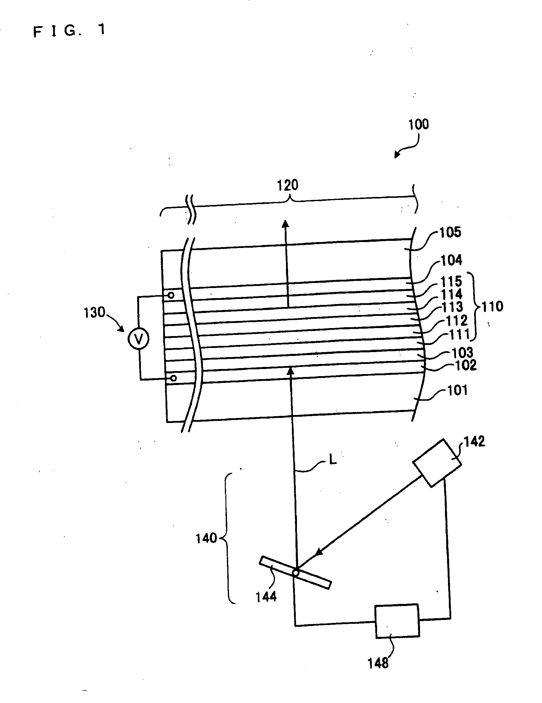
[0051]FIG. 1 is a schematic construction showing a display apparatus 100 according to Exemplary Embodiment 1 of the present invention. In this exemplary embodiment, the construction of the display apparatus 100 and a control by control light will be first described, and practicable image displays based on the display apparatus 100 will be subsequently described. The display apparatus 100 is constructed of a display panel 120, a power source 130, and an optical system for control light, 140. The display panel 120 displays an image by causing an organic EL layer 110 to emit light.

[0052] A substrate 101 is a parallel flat plate which is made of a glass member, a polymer member or the like which is optically transparent. A first transparent electrode layer 102 being optically transparent, and a conductivity-variable layer 103 are successively stacked on the substrate 101. The first transparent electrode layer 102 can be made of an ITO film. The conductivity-variable layer 103 has its e...

exemplary embodiment 2

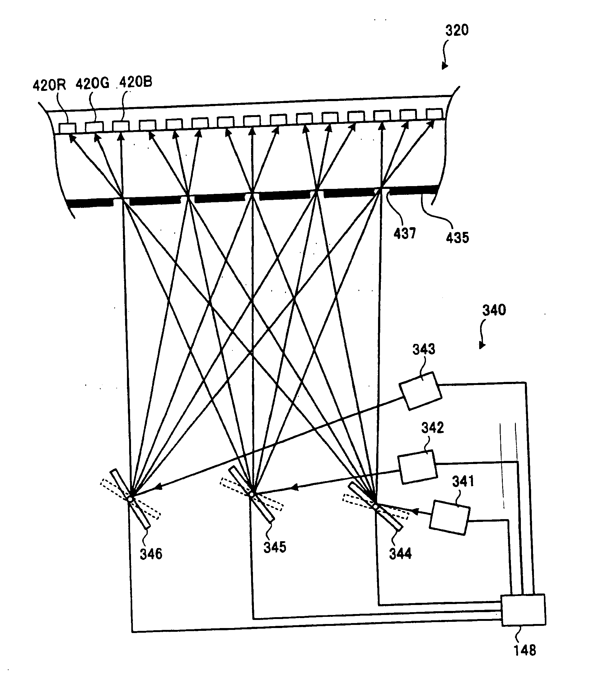
[0072]FIG. 3 is a schematic showing a display apparatus 300 according to Exemplary Embodiment 2 of the present invention. The same signs are assigned to the same portions as in the display apparatus 100 of the foregoing exemplary embodiment 1, and they shall not be repeatedly described. The display apparatus 300 of this exemplary embodiment serves to observe light which is caused to exit from a display panel 320 mounted on a frame 360. An optical system for control lights 340 is accommodated in the frame 360. The display panel 320 features that an organic EL layer forms a structure in which it is divided into a plurality of regions corresponding to pixels.

[0073] A first light source portion for control light 341, a second light source portion for control light 342 and a third light source portion for control light 343 generate the first control light L1, second control light L2 and third control light L3, respectively. Besides, the control lights L1, L2 and L3 (shown in FIGS. 3 and...

exemplary embodiment 3

[0101]FIG. 9 is a schematic showing a display panel 920 according to Exemplary Embodiment 3 of the present invention. The same signs are assigned to the same portions as in the display apparatus 300 of the foregoing exemplary embodiment 2, and they shall not be repeatedly described. The display panel 920 in this exemplary embodiment features that the region of a reflection electrode 911 corresponding to each pixel is larger than the region of the part of an organic EL layer 910 as is partitioned by banks 925. The organic EL layer 910, is constructed of the reflection electrode 911, an ITO film 412, a hole transport layer 413, an organic light emission layer 414 and an electron transport layer 415. Similar to the reflection electrode 111 in Exemplary Embodiment 1, the reflection electrode 911 can be constructed by evaporating a metal, for example, aluminum (Al). Likewise to the bank 425 in Exemplary Embodiment 2, the bank 925 is an electrical insulating member which is provided to be...


PUM


Abstract

Exemplary embodiments of the present invention provide a display panel or the like in which it is easy to enlarge a size of the display panel. A display panel according to exemplary embodiments includes a first transparent electrode layer and a second transparent electrode layer which are optically transparent, a conductivity-variable layer which is provided on the first transparent electrode layer, and an electroluminescent layer which is provided between the conductivity-variable layer and the second transparent electrode layer, and which emits light by applying a voltage thereto.

Description

BACKGROUND OF THE INVENTION [0001] 1. Field of Invention [0002] Exemplary embodiments of the present invention relate to a display panel, a method of manufacturing a display panel, and a display apparatus. More particularly, the exemplary embodiments relate to the technology of a display panel for use in a display apparatus which is controllable by light. [0003] 2. Description of Related Art [0004] A related art organic electroluminescence (hereinbelow “EL”) display, for example, can be employed as an image display apparatus. For example, technology of the organic EL display is disclosed in “Organic EL materials and Displays”, CMC, ISBN: 4-88231-284-0 C3054, Chapter 19, “Driving method for Organic EL display”, Shingo Kawashima, pp. 279-289. SUMMARY OF THE INVENTION [0005] The organic EL display in the related art is such that thin film transistor (hereinbelow “TFT”) elements made from low-temperature poly-silicon, amorphous silicon or the like are disposed in regions which correspon...

Claims


Application Information

Patent Timeline
IPC IPC(8): H05B33/26G02B26/00G09F9/00G09F9/30G09G3/10H01L27/14H01L27/15H01L27/32H01L51/50H01L51/52H04N5/70H04N9/30H05B33/10H05B33/12H05B33/14H05B33/22H05B33/24
CPCH01L27/3211H01L27/3281H04N9/30H01L51/5203H01L27/3295H10K59/35H10K59/10H10K59/17H10K59/173H10K50/80H10K59/805H05B33/26H05B33/10H10K50/805
Inventor YONEKUBO, MASATOSHITAKEDA, TAKASHIYAMAZAKI, TETSURO
Owner 138 EAST LCD ADVANCEMENTS LTD
Why Eureka
Try Eureka