Generating device having magneto generator

a technology of generating device and magneto generator, which is applied in the direction of electric generator control, dynamo-electric converter control, instruments, etc., can solve the problems of increasing the size and weight the inability of the battery to be charged during a low speed rotation of the engine, and the insufficient output of the magneto generator

Active Publication Date: 2005-05-05
MAHLE INT GMBH
View PDF6 Cites 53 Cited by
  • Summary
  • Abstract
  • Description
  • Claims
  • Application Information

AI Technical Summary

Benefits of technology

[0012] Thus, an object of the invention is to provide a generating device that can generate an increased output from a magneto generator during a low speed rotation, and also generate a sufficient output from the magneto generator in middle and high rotation ranges, without increasing a size of the generator, to control to keep a generation output at a target value from a low speed rotation range to the high speed rotation range without any trouble.

Problems solved by technology

When a compact magneto generator is used, a rotational speed at which a battery starts to be charged is high, and thus the battery cannot be charged during a low speed rotation of the engine.
For allowing the battery to be charged even during the low speed rotation of the engine, increasing the number of turns of the armature coil without changing a structure of the magneto generator can be considered, which, however, causes an insufficient output to be obtained from the magneto generator during a high speed rotation of the engine.
For generating a sufficient output from the magneto generator during the low speed rotation of the engine, and also obtaining a sufficient output from the magneto generator during the high speed rotation of the engine, an armature coil with many turns needs to be wound by using a conductor with a large area, which increases a size and a weight of the magneto generator.
A large magneto generator unpreferably increases a weight of the engine to cause poor fuel economy, or increases inertia of the engine to cause poor acceleration performance.. Further, the large magneto generator cannot be mounted to a compact vehicle such as a motorcycle.
However, the chopper control can increase the output of the generator only in the low speed rotation range of the engine, and the generation output cannot be increased in middle and high speed rotation range by the chopper control.
When the magneto generator is driven by an internal combustion engine for a vehicle, a problem occurs that the output of the generator becomes excessive during the high speed rotation of the engine.
However, when the short circuit type regulator is used, a high short circuit current passes through the armature coil in voltage control, and thus the armature coil unpreferably generates much heat.
The drive control of the magneto generator can prevent the output of the magneto generator from becoming excessive during the high speed rotation of the engine without using the short circuit type regulator, but an advantage of increasing the output of the magneto generator during the low speed rotation cannot be reasonably expected from the drive control.

Method used


Image

  • Generating device having magneto generator
  • Generating device having magneto generator
  • Generating device having magneto generator

Examples


first embodiment

[First Embodiment]

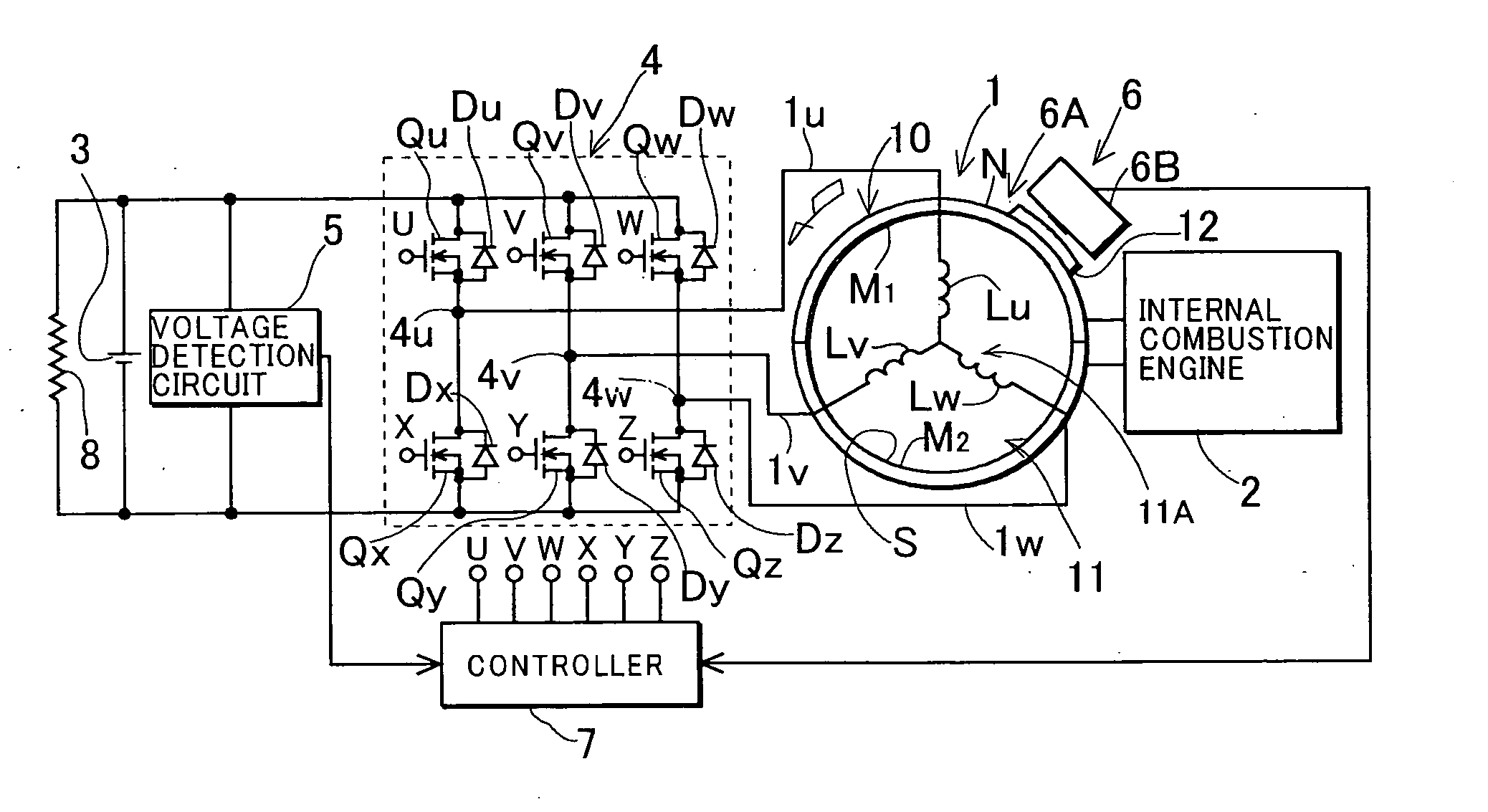
[0047]FIG. 1 shows an entire construction of an embodiment in which the invention is applied to a generating device that uses a magneto generator having a stator with a three-phase armature coil to charge a battery. In FIG. 1, a reference numeral 1 denotes a magneto generator driven by an internal combustion engine 2, and 3 denotes a battery. A reference numeral 4 denotes an AC / DC conversion unit provided between the magneto generator 1 and the battery 3, which has a rectifier and an inverter circuit. A reference numeral 5 denotes a voltage detection circuit that detects a voltage output from the magneto generator 1 through the rectifier circuit in the conversion unit 4 (a voltage across the battery), and 6 denotes a signal generating device that generates pulses when a rotational angle position of a magnet rotor of the magneto generator 1 matches a predetermined position. A reference numeral 7 denotes a controller having a microprocessor, and 8 denotes a load conn...

second embodiment

[Second Embodiment]

[0112] As described above, when the control mode is switched from the chopper control mode to the drive control mode, the charging current is estimated from the duty ratio of the chopper control to arithmetically operate the initial value of the phase angle of the AC control voltage of the drive control required for passing the charging current equal to the estimated charging current, while when the control mode is switched from the drive control mode to the chopper control mode, the charging current is estimated from the phase angle of the AC control voltage of the drive control to arithmetically operate the initial value of the duty ratio of the chopper control required for passing the charging current equal to the estimated charging current. This eliminates the need for providing a current detection circuit that detects the charging current of the battery when the voltage across the battery (the output voltage of the generator) is detected to control to keep th...

third embodiment

[Third Embodiment]

[0125] In a third embodiment of the invention, control mode switching means 23 is comprised so as to switch the control mode to the drive control mode when the rotational speed becomes higher than the set speed, the output of the magneto generator 1 becomes lower than a set value, and the duty ratio of the chopper control reaches a value that maximizes the output current of the magneto generator 1, in a state where the rotational speed of the magneto generator 1 is lower than the set speed N1 in the control by the chopper control mode, and to switch the control mode to the chopper control mode when the rotational speed becomes lower than the set speed N1, the output of the magneto generator becomes lower than the set value, and the phase angle of the AC control voltage reaches a value that maximizes the output current of the magneto generator, in a state where the rotational speed is the set speed or higher in the control by the drive control mode.

[0126]FIG. 8 sho...


PUM


Abstract

A generating device that includes an AC/DC conversion unit having a rectifier circuit that rectifies an output of a magneto rotor and applies the output to a battery, and an inverter circuit that converts a voltage of the battery into an AC control voltage and applies the AC control voltage to an armature coil of the magneto generator, performs chopper control that controls switch elements of the inverter circuit so as to interrupt an output current of the magneto generator to control the output of the magneto generator when a rotational speed of the magneto generator is lower than a set speed, and performs drive control that applies the AC control voltage from the battery through the inverter circuit to the armature coil when the rotational speed becomes higher than the set speed, and changes a phase angle of the AC control voltage to control the output of the magneto generator.

Description

TECHNICAL FIELD OF THE INVENTION [0001] The present invention relates to a generating device that converts an AC output of a magneto generator into a DC output and supplies the DC output to a load. BACKGROUND OF THE INVENTION [0002] A magneto generator is comprised of a magnet rotor, and a stator including an n-phase armature coil (n is an integer equal to or more than one) wound around an armature core having a magnetic pole portion facing a magnetic pole of the magnet rotor. Such a magneto generator is mounted to an internal combustion engine for driving a vehicle, and often used for charging a battery in the vehicle. [0003] When the battery is charged with a rectified output of the magneto generator driven by the internal combustion engine, the battery does not start to be charged until a rotational speed of the engine increases to a certain extent and a no-load output voltage of the magneto generator exceeds a voltage across the battery. When a compact magneto generator is used,...

Claims


Application Information

Patent Timeline
Patent Type & Authority Applications(United States)
IPC IPC(8): H02P9/04H02P9/02
CPCH02M7/53871H02K11/0073H02K29/08H02P9/02H02K11/33
Inventor MURAMATSU, SHUICHISUZUKI, HIDEAKINAKAGAWA, MASANORITAKAHASHI, MASAKATSU
Owner MAHLE INT GMBH
Why Eureka
Try Eureka