Film acoustically-coupled transformer with increased common mode rejection

a technology of acoustically coupled transformers and common mode, which is applied in the direction of impedence networks, electrical equipment, and semiconductor devices, can solve the problems of coil-based transformers becoming impractical, not all transformers have all of these properties, and the autotransformer does not provide electrical isolation, etc., and achieves the effect of increasing the common-mode rejection ratio

Active Publication Date: 2005-05-05
AVAGO TECH INT SALES PTE LTD
View PDF98 Cites 131 Cited by
  • Summary
  • Abstract
  • Description
  • Claims
  • Application Information

AI Technical Summary

Benefits of technology

[0016] In a first aspect, the invention provides a film acoustically-coupled transformer (FACT) that comprises a first decoupled stacked bulk acoustic resonator (DSBAR) and a second DSBAR. Each DSBAR comprises a lower film bulk acoustic resonator (FBAR), an upper FBAR stacked atop the lower FBAR, and an acoustic decoupler between the FBARs. Each FBAR comprises opposed planar electrodes and a piezoelectric element between the electrodes. The FACT additionally comprises a first electrical circuit connecting the lower FBAR of the first DSBAR to the lowe

Problems solved by technology

However, not all transformers have all of these properties.
For example, an autotransformer does not provide electrical isolation.
At UHF and microwave frequencies, coil-based transformers become impractical due to such factors as losses in the core, losses in the windings, capacitance between the windings, and a difficulty to make them small enough to prevent wavelength-related problems.
Transformers also exist that are based on micro-machined coupled coils sets and are small enough that wavelength effects are unimportant.
However such transformers have issues with high insertion loss.
All the transformers just described for use at UHF and microwave frequencies have dimensions that make them less desirable for use in modern miniature, high-density applications such as cellular telephones.
Such transformers also tend to be high in cost because they are not capable of being manufactured by a batch process and because they

Method used


Image

  • Film acoustically-coupled transformer with increased common mode rejection
  • Film acoustically-coupled transformer with increased common mode rejection
  • Film acoustically-coupled transformer with increased common mode rejection

Examples


embodiment 200

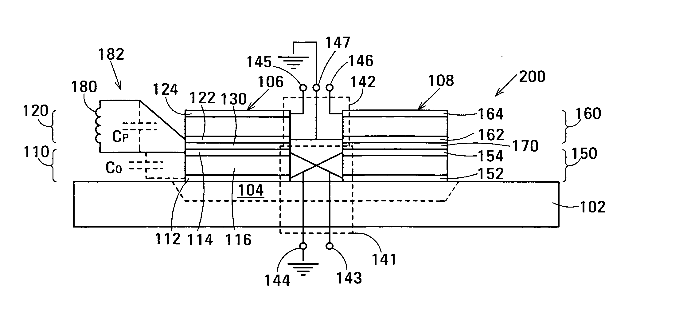
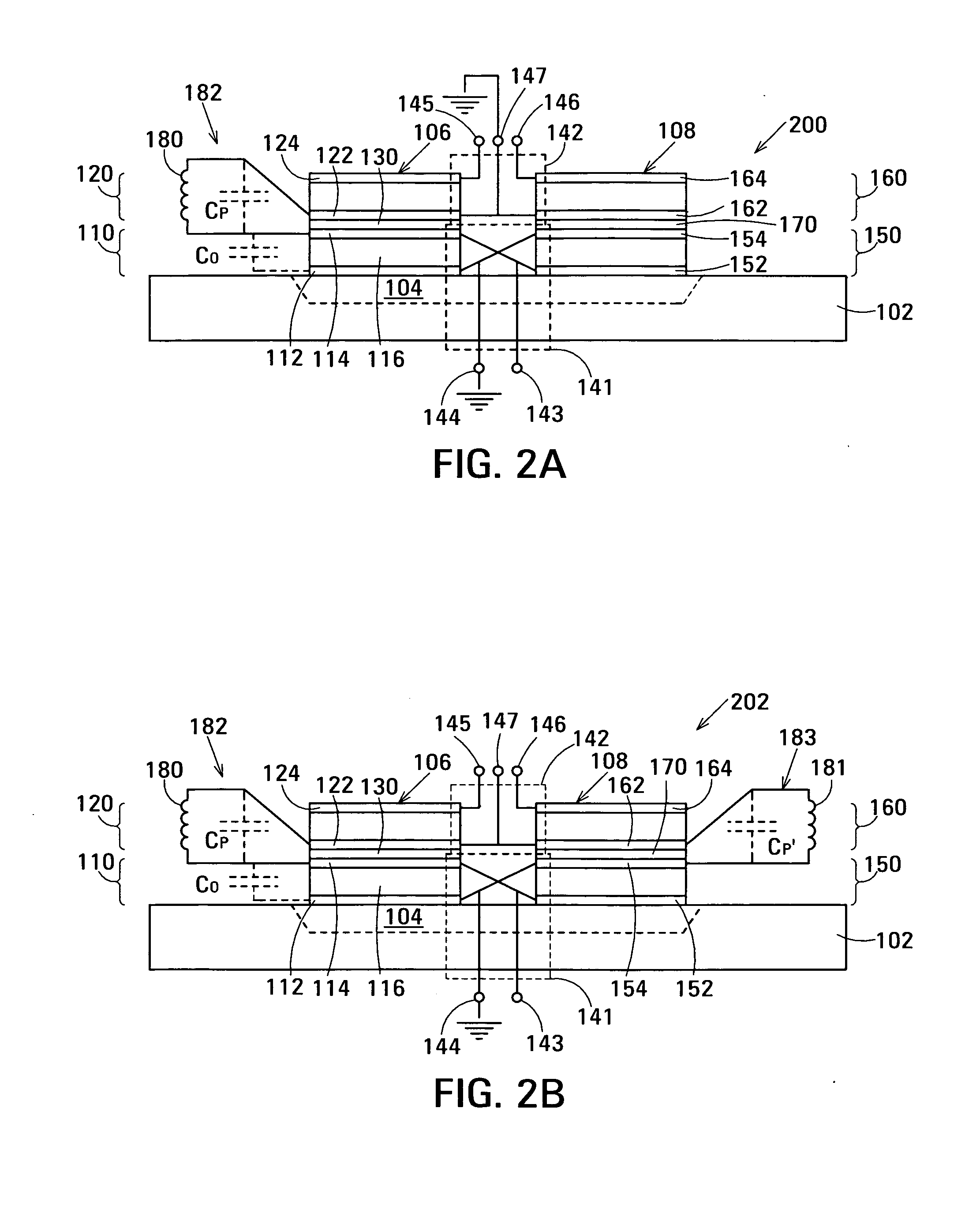
[0039]FIG. 2A is a schematic drawing showing an embodiment 200 of a film acoustically-coupled transformer (FACT) in accordance with the invention. FACT 200 is for use in an application similar to that described above with reference to FIG. 1B in which electrodes 112 and 154 connected to terminal 144 are grounded and electrodes 122 and 162 connected to center tap terminal 147 are also grounded. Elements of FACT 200 that correspond to elements of FACT 100 described above with reference to FIG. 1B are indicated by the same reference numerals and will not be described again here. In FACT 200, an inductor 180 is connected between electrode 114 and electrode 122 on opposite sides of acoustic decoupler 130. This connects inductor 180 in parallel with parasitic capacitor CP. Inductor 180 significantly increases the common-mode rejection ratio of FACT 200 relative to that of FACT 100 by reducing the current flow between electrical circuit 141 and electrical circuit 142. Inductor 180 addition...

embodiment 202

[0041]FIG. 2B is a schematic drawing showing an embodiment 202 of a FACT in accordance with the invention. FACT 202 is for use in an application similar to that described above with reference to FIG. 1C in which electrodes 112 and 124 are grounded and electrical circuit 142 is floating. Elements of FACT 202 that correspond to elements of FACT 100 described above with reference to FIG. 1B and of FACT 200 described above with reference to FIG. 2A are indicated by the same reference numerals and will not be described again here. FACT 202 has an inductor 180 connected between electrode 114 and electrode 122 on opposite sides of acoustic decoupler 130 and an inductor 181 connected between electrode 154 and electrode 162 on opposite sides of acoustic decoupler 170. Inductors 180 and 181 significantly increase the common-mode rejection ratio of FACT 202 relative to that of FACT 100 by reducing the current flow between electrical circuit 141 and electrical circuit 142. Inductor 180 addition...

embodiment 300

[0043] In FACT 200 shown in FIG. 2A, inductor 180 interconnects electrical circuit 141 and electrical circuit 142 at DC. As a result, FACT 200 does not provide electrical isolation between electrical circuit 141 and electrical circuit 142 at DC. FIG. 3A is a schematic drawing showing an embodiment 300 of a FACT in accordance with the invention that additionally provides electrical isolation between electrical circuits 141 and 142 at DC voltages up to the breakdown voltage of an isolating capacitor 184 connected in series with inductor 180. FACT 300 is for use in an application similar to that described above with reference to FIG. 1B in which electrodes 112 and 154 connected to terminal 144 are grounded and electrodes 122 and 162 connected to center tap terminal 147 are also grounded. Elements of the FACT 300 shown in FIG. 3A that correspond to elements of FACT 200 shown in FIG. 2A are indicated using the same reference numerals and will not be described again here.

[0044] In FACT 30...


PUM

PropertyMeasurementUnit
Massaaaaaaaaaa
Thicknessaaaaaaaaaa
Dielectric polarization enthalpyaaaaaaaaaa

Abstract

The film acoustically-coupled transformer (FACT) has a first and second decoupled stacked bulk acoustic resonators (DSBARs). Each DSBAR has a lower film bulk acoustic resonator (FBAR), an upper FBAR atop the lower FBAR, and an acoustic decoupler between them FBARs. Each FBAR has opposed planar electrodes and a piezoelectric element between the electrodes. A first electrical circuit interconnects the lowers FBAR of the first DSBAR and the second DSBAR. A second electrical circuit interconnects the upper FBARs of the first DSBAR and the second DSBAR. In at least one of the DSBARs, the acoustic decoupler and one electrode of the each of the lower FBAR and the upper FBAR adjacent the acoustic decoupler constitute a parasitic capacitor. The FACT additionally has an inductor electrically connected in parallel with the parasitic capacitor. The inductor increases the common-mode rejection ratio of the FACT.

Description

RELATED APPLICATION [0001] This disclosure is a Continuation-in-Part of U.S. patent application Ser. No. 10 / 699,481 of John D. Larson III and Richard Ruby. This application is also related to U.S. patent application Ser. No. ______ of John D. Larson III and Stephen Ellis entitled Pass Bandwidth Control in Decoupled Stacked Bulk Acoustic Resonator Devices (Agilent Docket No. 10040955-1) and U.S. patent application Ser. No. ______ of John D. Larson III, Richard Ruby and Stephen Ellis entitled Film Acoustically-Coupled Transformer (Agilent Docket No. 10041306-1), both filed on the filing date of this disclosure. The above applications are assigned to the assignee of this application and the disclosures of the above applications are incorporated into this application by reference.BACKGROUND [0002] Transformers are used in many types of electronic device to perform such functions as transforming impedances, linking single-ended circuitry with balanced circuitry or vice versa and providin...

Claims


Application Information

Patent Timeline
IPC IPC(8): H03H9/13H03H9/17H03H9/60
CPCH03H9/132H03H9/584Y10T29/42H03H9/605H03H9/587H01L2224/48091H01L2224/49175H01L2924/00014H03H9/60H03H9/0095
Inventor LARSON, JOHN D. IIISARKESHIK, NAGHMEHELLIS, STEPHEN L.
Owner AVAGO TECH INT SALES PTE LTD
Why Eureka
Try Eureka