Liquid crystal device and electronic apparatus using the same

Active Publication Date: 2005-05-05
BOE TECH GRP CO LTD
View PDF6 Cites 2 Cited by
  • Summary
  • Abstract
  • Description
  • Claims
  • Application Information

AI Technical Summary

Benefits of technology

[0024] In the liquid crystal device according to the first embodiment of the present invention, a predetermined forward scattering type polarizing plate is provided between the polarizing plate and the liquid crystal layer such that the transmission axis of the forward scattering type polarizing plate is perpendicular to the transmission axis of the polarizing plate. Therefore, in the white display mode, light is diffused while passing through the forward scattering polarizing plate, resulting in a bright display. On the other hand, in the black display mode, since light is minimally diffused while passing through the forward scattering polarizing plate, light can be completely shielded by the polarizing plate, thereby improving contrast.
[0034] Moreover, an electronic apparatus according to the third embodiment of the present invention makes it possible to display a high-contrast and bright image by comprising the liquid crystal device according to any one of the above-mentioned aspects.

Problems solved by technology

However, in the liquid crystal device shown in FIG. 6, since all light components are scattered by an isotropic forward scattering plate, light scattering occurs even in a black display mode.
As a result, some light components pass through the polarizing plate, and thus light cannot be completely shielded, thereby generating an image blur and the deterioration of contrast.
In the meantime, the main object of the illustrated conventional example is to improve the utilization efficiency of light using a thin liquid crystal device equipped with a scattering polarizing plate, but high contrast is not obtained by the liquid crystal device.

Method used


Image

  • Liquid crystal device and electronic apparatus using the same
  • Liquid crystal device and electronic apparatus using the same
  • Liquid crystal device and electronic apparatus using the same

Examples


first embodiment

[0041] First Embodiment

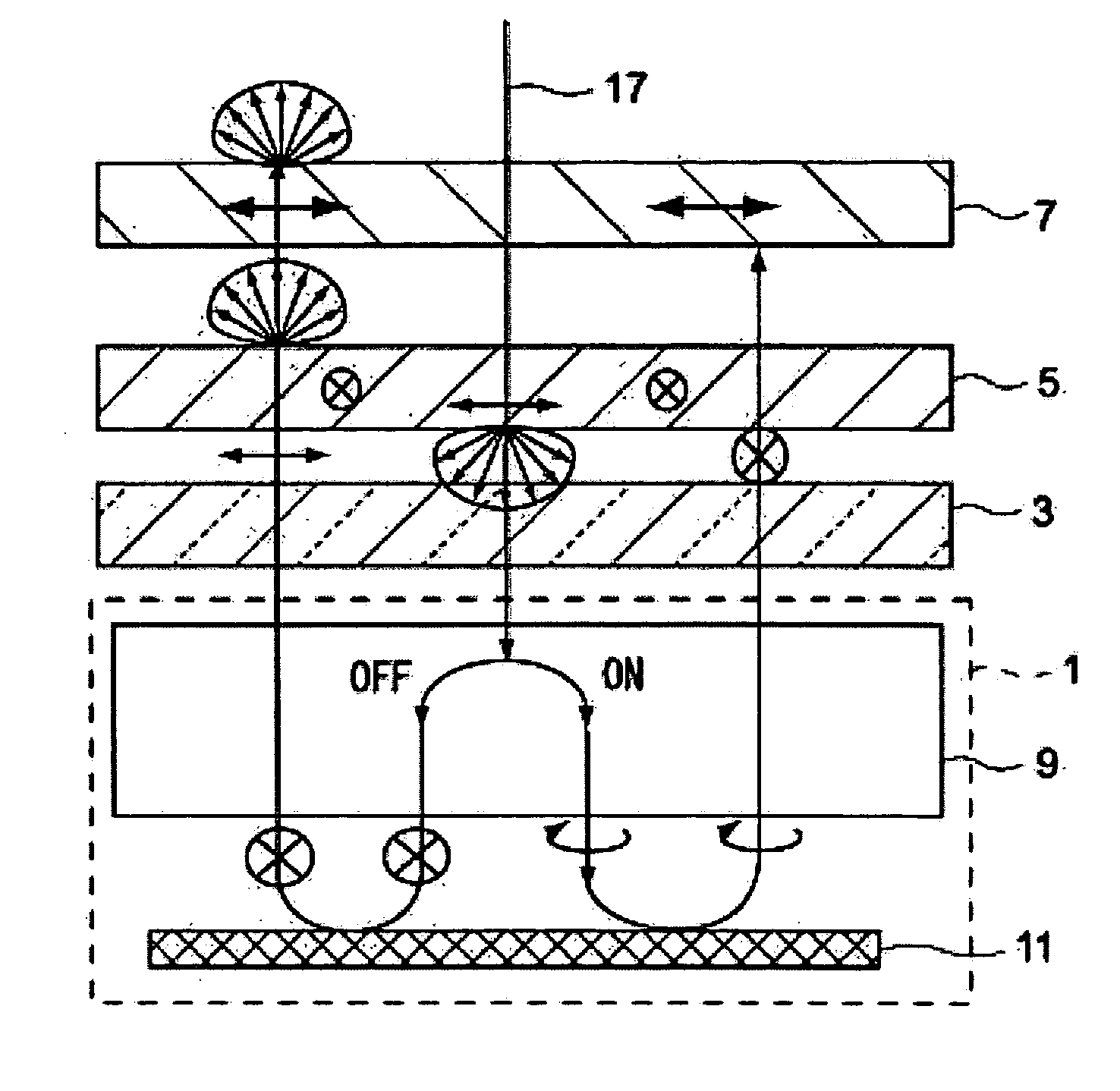
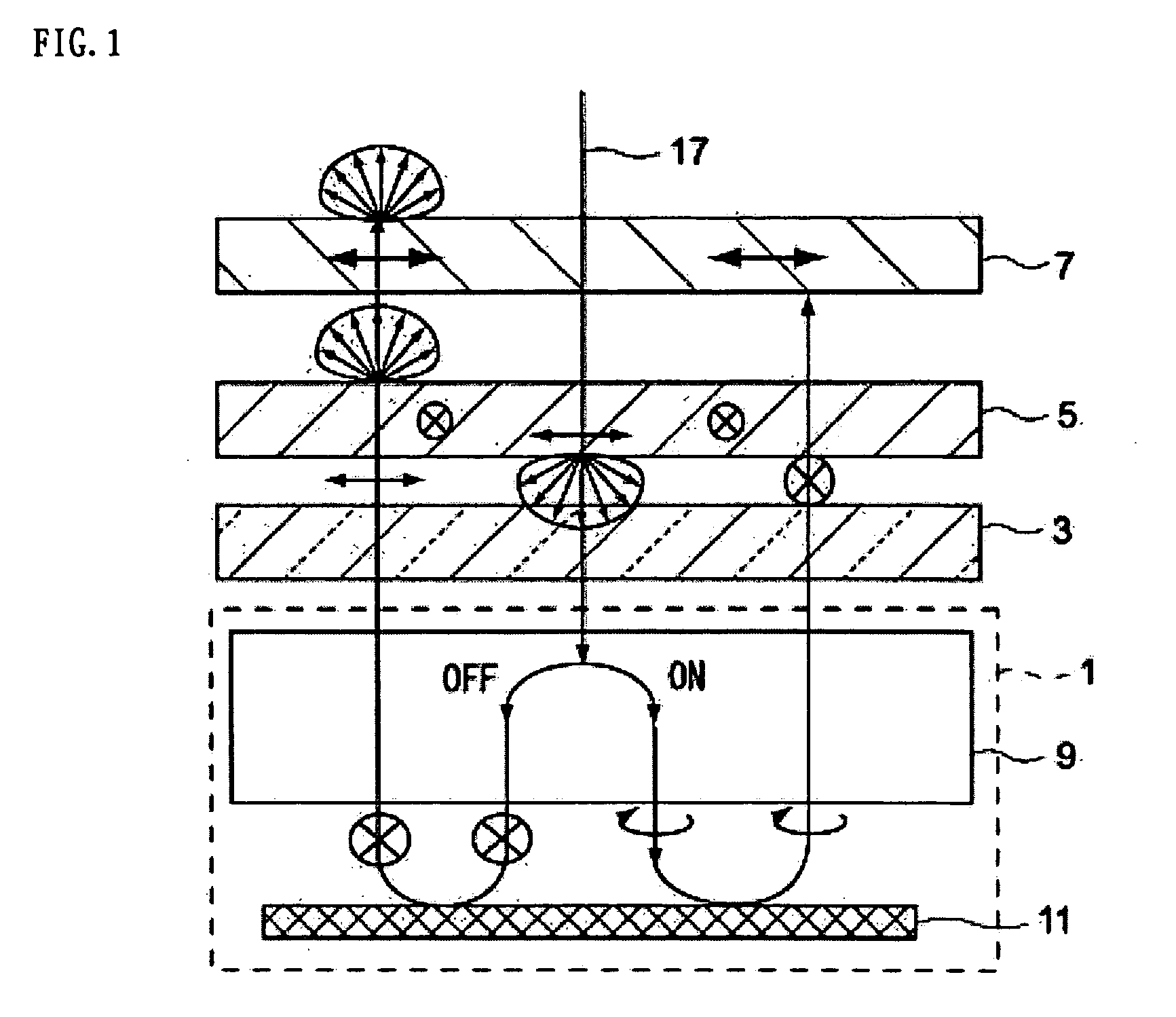
[0042] In a liquid crystal device according to the first embodiment, as shown in FIG. 1, external light incident on a liquid crystal layer through a polarizing plate is reflected from a reflecting layer and then exits to the outside through the liquid crystal layer and the polarizing plate, thereby displaying an image. A forward scattering type polarizing plate having a transmission axis and a diffusing axis is provided between the polarizing plate and the liquid crystal layer such that the transmission axis of the forward scattering type polarizing plate is perpendicular to the transmission axis of the polarizing plate.

[0043]FIG. 1 is an explanatory diagram illustrating the basic structure of the liquid crystal device according to the first embodiment of the present invention. As the liquid crystal device according to the present embodiment, a reflective liquid crystal device is used in which external light incident on the liquid crystal layer through the po...

second embodiment

[0060] Second Embodiment

[0061]FIG. 3 is an explanatory diagram illustrating the basic structure of a liquid crystal device according to a second embodiment of the present invention. In FIG. 3, the same components as those in FIG. 1 have the same reference numerals, and the description thereof will be omitted for the simplicity of explanation.

[0062] The second embodiment relates to a transflective liquid crystal device having a transmissive mode in which an image is displayed using the light emitted from a light source and a reflective mode in which an image is displayed using external light.

[0063] As shown in FIG. 3, the liquid crystal device according to the present embodiment comprises a backlight 21 arranged on the surface of a reflecting plate 19, a polarizing plate 23 arranged on the surface of the backlight 21 for passing only the light component polarized in one direction, and a retardation plate (a quarter-wave plate)25 arranged on the surface of the polarizing plate 23.

[...

third embodiment

[0072] Third Embodiment

[0073]FIG. 4 is an explanatory diagram illustrating a third embodiment of the present invention. The third embodiment relates to a transflective color liquid crystal device using color filters.

[0074] As shown in FIG. 4, the color liquid crystal device according to the third embodiment comprises a color filter substrate 37 and a counter substrate 38 opposite to each other, a forward scattering type polarizing plate 39 provided on the surface of the counter substrate 38 (on the side opposite to the color filter substrate 37), a first retardation plate 41 provided on the surface of the forward scattering type polarizing plate 39, a second retardation plate 43 provided on the surface of the first retardation plate 41, and a polarizing plate 45 provided on the surface of the second retardation plate 43.

[0075] In addition, the color liquid crystal device further comprises a retardation plate (a quarter-wave plate) 47 provided on one surface of the color filter sub...


PUM


Abstract

A reflective liquid crystal device is provided in which external light incident on a liquid crystal layer through a polarizing plate is reflected from a reflecting layer and then exits to the outside through the liquid crystal layer and the polarizing plate to display an image. A forward scattering type polarizing plate having a transmission axis and a diffusion axis is arranged between the polarizing plate and the liquid crystal layer such that the transmission axis of the forward scattering type polarizing plate is perpendicular to the transmission axis of the polarizing plate.

Description

RELATED APPLICATIONS [0001] This application claims priority to Japanese Patent Application No. 2003-337817 filed Sep. 29, 2003 which is hereby expressly incorporated by reference herein in its entirety. BACKGROUND [0002] 1. Technical Field [0003] The present invention relates to a liquid crystal device having a reflective or transflective display element and an electronic apparatus using the same, and more specifically, to a liquid crystal device capable of displaying a bright and high-contrast image and to an electronic apparatus using the same. [0004] 2. Background Art [0005] In general, conventional liquid crystal devices have a structure in which a liquid crystal layer composed of liquid crystal molecules is interposed between a first substrate and a second substrate opposite to each other, and two polarizing plates are arranged in a spaced relation so as to interpose the liquid crystal layer therebetween. A liquid crystal device has been suggested in which a light scattering l...

Claims


Application Information

Patent Timeline
IPC IPC(8): F21V8/00G02F1/133G02F1/1335G02F1/13363G02F1/1347
CPCG02F1/133504G02F2203/02G02F1/133528G02F1/1335
Inventor IIJIMA, CHIYOAKI
Owner BOE TECH GRP CO LTD
Why Eureka
Try Eureka