Method of Manufacturing, Including Method of Inspecting, Fluid-Dynamic-Pressure Bearing Units

Active Publication Date: 2005-05-05
NIPPON DENSAN CORP
View PDF2 Cites 10 Cited by
  • Summary
  • Abstract
  • Description
  • Claims
  • Application Information

AI Technical Summary

Benefits of technology

[0015] An object of the present invention is to obviate problems originating in air bubbles being generated within oil charged into the bearing clearances in fluid-dynamic-pressure bearing units, before such problems occur. More specifically, an object of the invention is to make available a method of manufacturing fluid-dynamic-pressure bearing units, and a mo

Problems solved by technology

This is thought to originate in air, slight though it may be, remaining dissolved within the oil even after having undergone the degassing process, because even with the vacuum chamber being pumped down to a vacuum level, artificially creating a perfect vacuum state is impossible.
Air bubbles becoming manifest during the oil-charging procedure can hinder the smooth supply of oil from the vacuum chamber that stores oil to the vacuum chamber that holds the bearing unit, or, at the stage in which the oil has arrived inside the vacuum chamber that holds the bearing unit, can foam the oil such that the oil spouts out and sticks to the bearing unit and the vacuum-chamber interior, making it necessary to wipe the oil off, and such consequences cause a drop-off in productivity.
Moreover, if the motor is run with air bubbles within the oil mixed in as they are, eventually either of two of problems will arise.
One affects the endurance and reliability of the motor and is a problem of the air bubbles expanding in volume—due, for example, to a rise in temperature—and causing the oil to leak out to the bearing-unit exterior.
The other affects the rotational precision of the motor and is a problem of incidents of vibration or a problem of deterioration from NRRO (non-repeatable runout), due to the air bubbles coming into contact with the dynamic-pressure-generating grooves provided in the bearings.
Add

Method used


Image

  • Method of Manufacturing, Including Method of Inspecting, Fluid-Dynamic-Pressure Bearing Units
  • Method of Manufacturing, Including Method of Inspecting, Fluid-Dynamic-Pressure Bearing Units
  • Method of Manufacturing, Including Method of Inspecting, Fluid-Dynamic-Pressure Bearing Units

Examples


Embodiment Construction

[0024] The object of obviating problems originating in air bubbles being generated within oil charged into the bearing clearances in fluid-dynamic-pressure bearing units, before such problems occur, was realized without increasing operational man-hours needed or complicating the operational steps. The invention also accomplished the other object, which is to make it possible to single out the causative source of air bubbles in instances in which the generation of air bubbles is detected, without increasing man-hours needed or complicating the steps in the process.

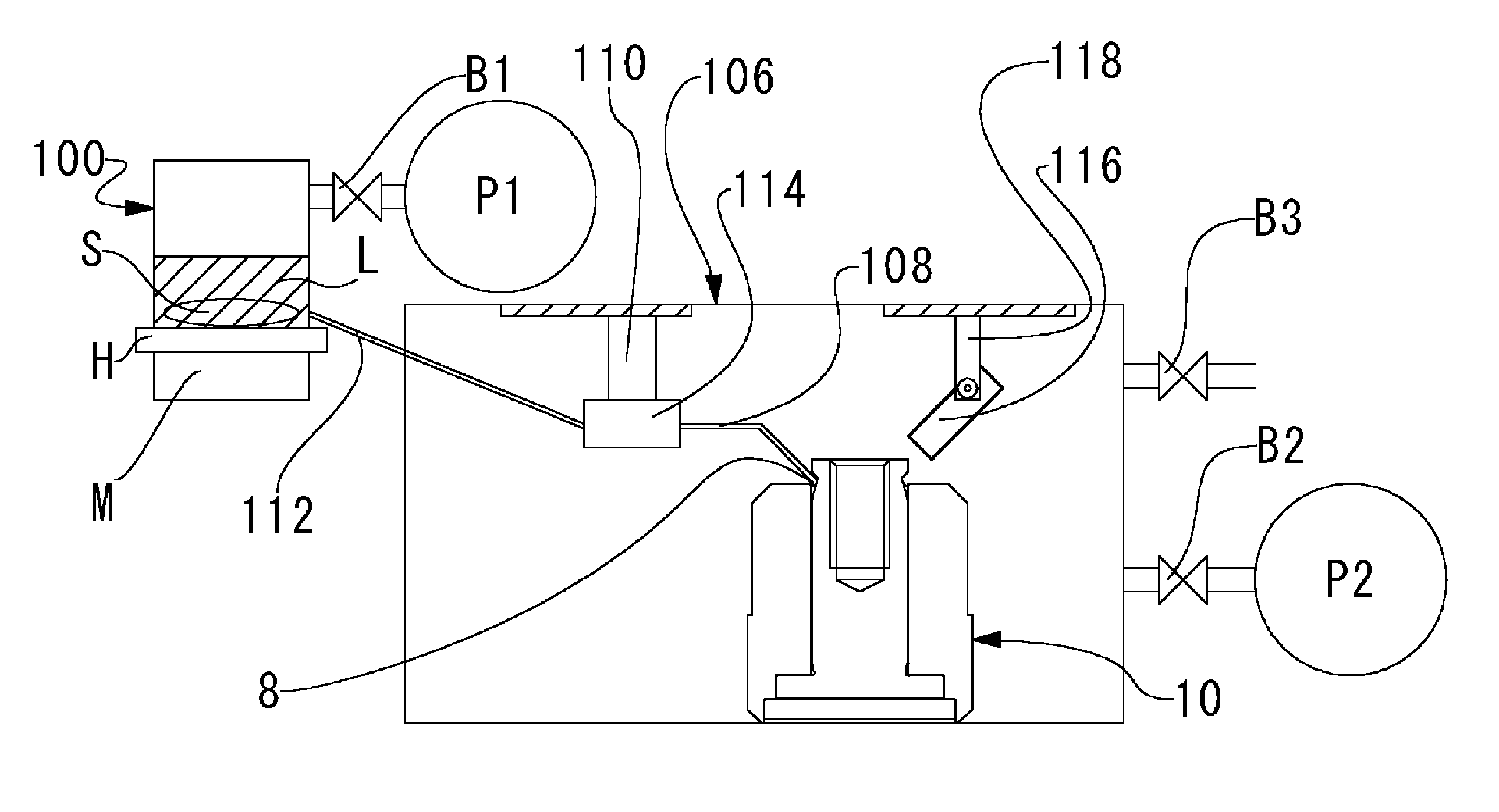
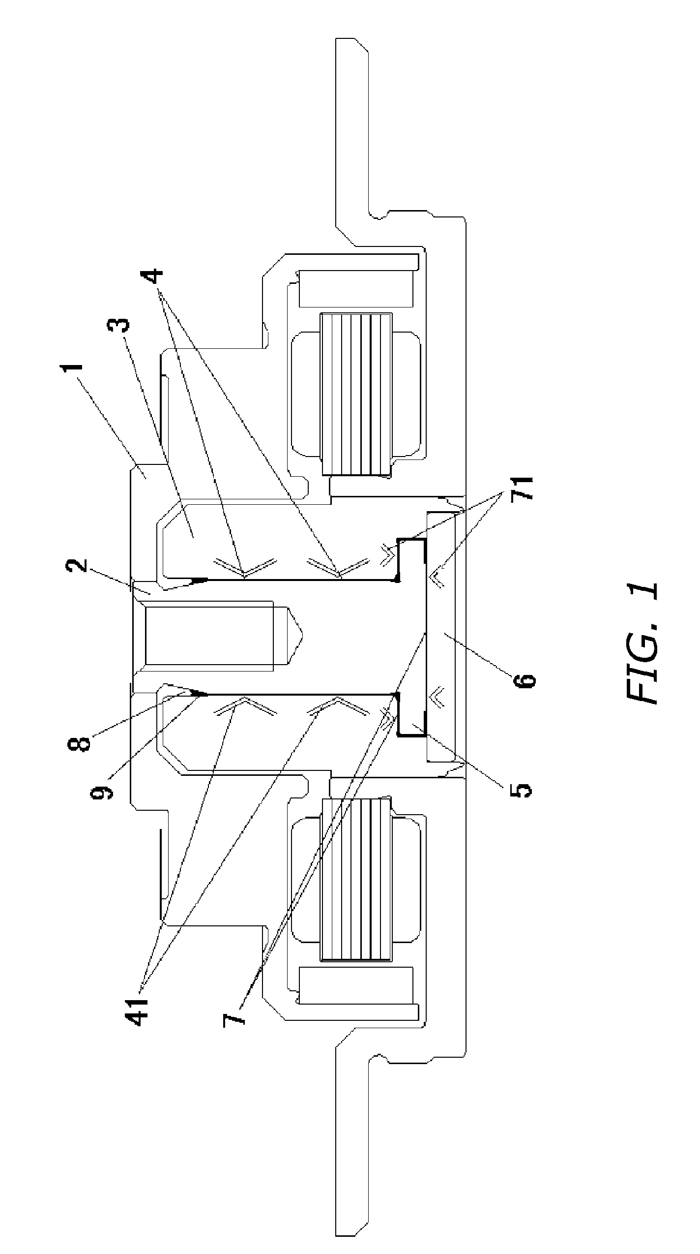
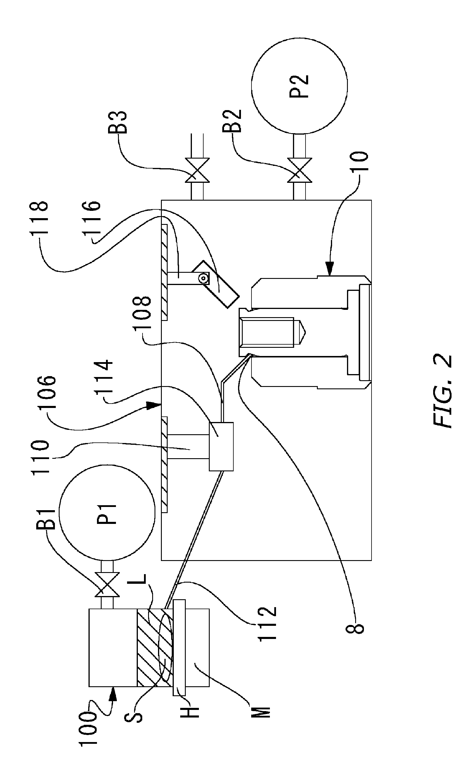
[0025] Below, reference is made to the appended drawings to discuss a method of manufacturing fluid-dynamic-pressure bearing units according to the present invention. A fluid-dynamic-pressure bearing unit 10 has the same configuration as the fluid-dynamic-pressure bearing shown in FIG. 1 and therefore, the configuration thereof is not elaborated upon to avoid repetitive description.

[0026] In a method according to the pres...


PUM

PropertyMeasurementUnit
Temperatureaaaaaaaaaa
Pressureaaaaaaaaaa
Magnetic fieldaaaaaaaaaa

Abstract

Fluid-dynamic-pressure bearing manufacturing method for more efficient and fail-safe degassing of bearing oil. Method makes it possible to prevent the generation of air bubbles in the course of an oil-charging operation that amounts to a step following degassing, and to single out the causative source of air bubbles when their generation has been detected. At the same time oil that is under a reduced-pressure environment within an oil-storing vacuum chamber is vacuum-degassed, immersed within the oil a stirrer for agitating and degassing the oil is rotated by indirect drive means, and the oil after having been degassed is supplied to a vacuum chamber where a fluid-dynamic-pressure bearing unit is retained—which has been pumped down to a pressure below the pressure within the oil-storing vacuum chamber—and is charged into the bearing clearances by raising the internal pressure of the bearing-retaining vacuum chamber.

Description

BACKGROUND OF THE INVENTION [0001] 1. Technical Field [0002] The present invention relates to methods of manufacturing fluid-dynamic-pressure bearing units employed as bearing devices in applications such as spindle motors for hard-disk drives, and to motors employing such fluid-dynamic-pressure bearing units. [0003] 2. Description of the Related Art [0004] As bearings for motors in which high rotational precision is demanded—as is the case with spindle motors employed in disk drives that drive recording disks such as hard disks, and with motors for driving the polygonal mirrors of laser printers—in order to support the shaft and sleeve letting one rotate relative to the other, fluid-dynamic-pressure bearing units that employ the fluid pressure of a lubricant such as oil intervening in between the two have variously been proposed to date. [0005] One example of a motor that employs such fluid-dynamic-pressure bearing units is illustrated in FIG. 1. This conventional dynamic-pressure-...

Claims


Application Information

Patent Timeline
IPC IPC(8): F16C17/10F16C33/10F16C33/14G11B19/20H02K7/08
CPCF16C17/107F16C33/107Y10T29/49639Y10T29/49636Y10T29/49702F16C2370/12
Inventor SUMI, SHIGEHARUHIROSHI, JYOICHIANDO, HIRONORI
Owner NIPPON DENSAN CORP
Why Eureka
Try Eureka