Systems and methods for calibrating coil sensitivity profiles

a technology of coil sensitivity and calibration method, which is applied in the field of magnetic resonance imaging (mri) systems, can solve the problems of insufficient update, large overhead in calibration time for calibration imaging steps, and inability to accurately update the status of the calibration image,

Inactive Publication Date: 2005-05-05
GE MEDICAL SYST GLOBAL TECH CO LLC +1
View PDF4 Cites 23 Cited by
  • Summary
  • Abstract
  • Description
  • Claims
  • Application Information

AI Technical Summary

Problems solved by technology

However, the calibration imaging steps may incur significant calibration time overhead and the diagnostic imaging quality may suffer because images produced by the calibration steps a) may not provide coil sensitivity information at signal voids where there are no spins, or b) may lack adequate update to capture profile alterations due to

Method used


Image

  • Systems and methods for calibrating coil sensitivity profiles
  • Systems and methods for calibrating coil sensitivity profiles
  • Systems and methods for calibrating coil sensitivity profiles

Examples


Embodiment Construction

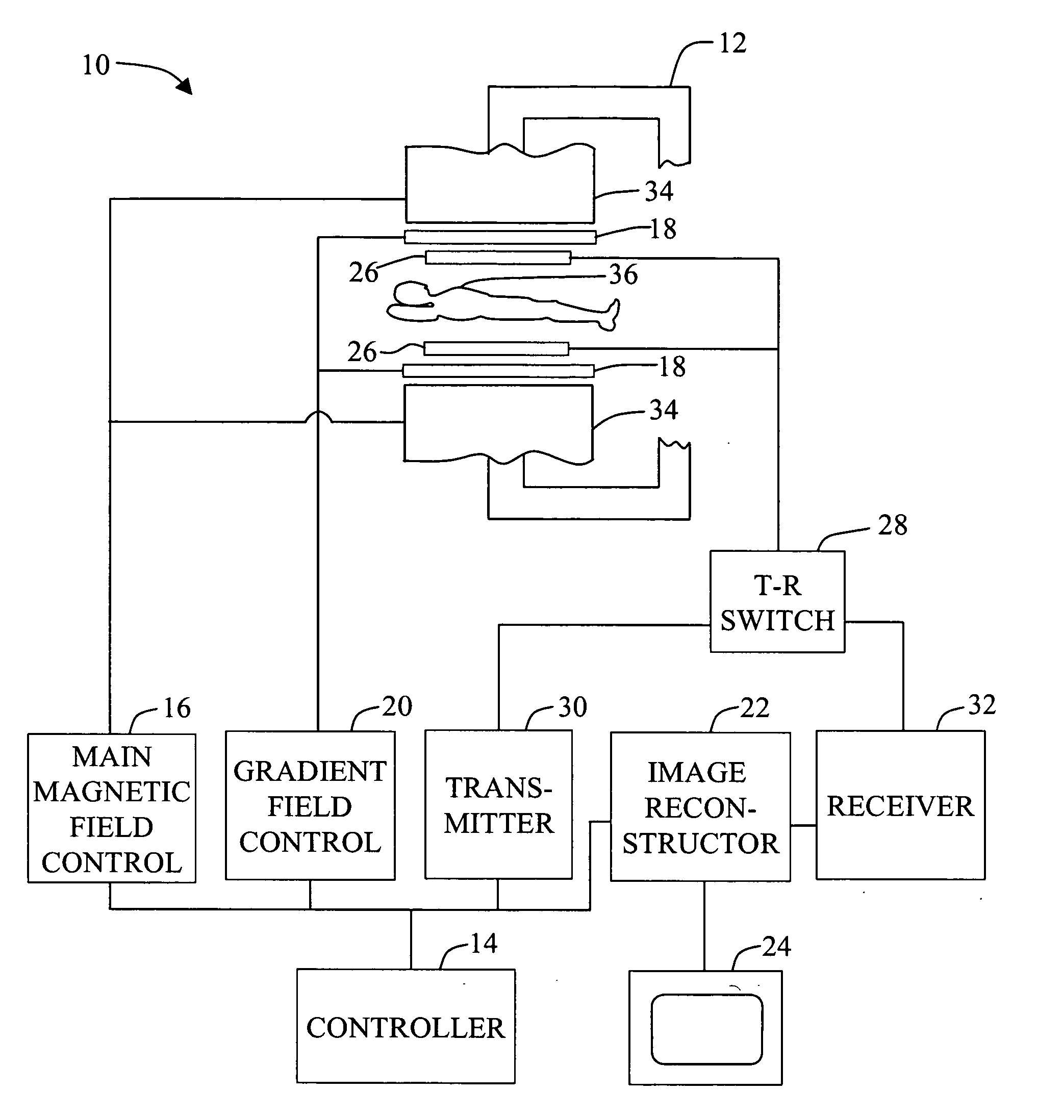
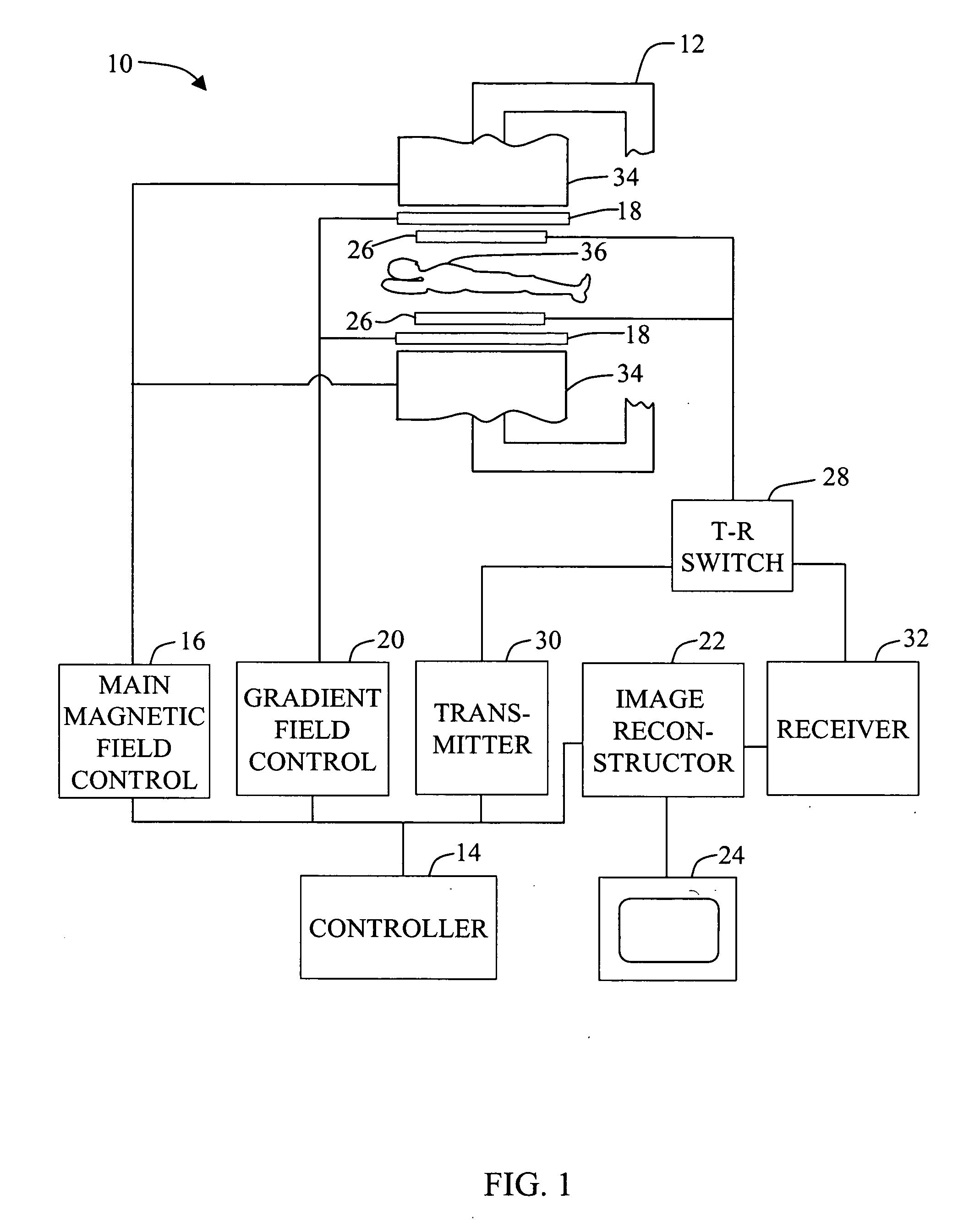
[0015]FIG. 1 illustrates an embodiment of a magnetic resonance imaging (MRI) system 10 in which systems and methods for calibrating coil sensitivity profiles are implemented. MRI system 10 includes an electromagnet 12, a controller 14, a main magnetic field control 16, a gradient coil sub-system 18, a gradient field control 20, an image reconstructor 22, a display device 24, coil arrays 26, a T-R (transmit-receive) switch 28, a transmitter 30, and a receiver 32.

[0016] The term controller, as used herein, is not limited to just those integrated circuits referred to in the art as computers, but broadly refers to processors, microcontrollers, microcomputers, programmable logic controllers, application specific integrated circuits, and other programmable circuits, and these terms are used interchangeably herein. Although a C-type electromagnet 12 is illustrated, other shapes of electromagnets, such as an electromagnet that completely surrounds a subject 36, such as a patient or a phant...


PUM


Abstract

A method for calibrating coil sensitivity profiles is described. The method includes generating reference sensitivity maps for each coil, imaging a subject, interleaving, with the imaging of the subject, imaging of at least one fiducial mark provided with each coil, and deriving, based on the coil positioning and coil loading, actual sensitivity maps from the reference sensitivity maps.

Description

BACKGROUND OF THE INVENTION [0001] This invention relates generally to magnetic resonance imaging (MRI) systems and more particularly, to systems and methods for calibrating coil sensitivity maps or profiles of coils used within MRI systems. [0002] MRI is a technique that is capable of providing three-dimensional imaging of an object, such as the heart or brain, of a patient. At least some known MRI systems include a main or primary magnet that provides a polarizing magnetic field Bo, and include gradient coils and radio frequency (RF) coils, which are used for spatial encoding, exciting and detecting nuclei of the patient during imaging. Typically, the main magnet provides a homogeneous magnetic field in an internal region within the main magnet, for example, within an air space defined within a solenoid, or within an air gap defined between magnetic pole faces of a C-type magnet. The patient or an object to be imaged is positioned in the homogeneous field region such that the grad...

Claims


Application Information

Patent Timeline
IPC IPC(8): A61B5/055G01R33/561
CPCG01R33/5611
Inventor ZHU, YUDONGDUMOULIN, CHARLES LUCIAN
Owner GE MEDICAL SYST GLOBAL TECH CO LLC
Why Eureka
Try Eureka