Magnetic resonance imaging device and transmitting sensitivity distribution calculation method

a magnetic resonance imaging and transmitting sensitivity technology, applied in the field of magnetic resonance imaging apparatuses, can solve the problems of image non-uniformity and unevenness in abdominal images, and achieve the effect of high degree of precision and high quality of images

Active Publication Date: 2013-04-04
FUJIFILM HEALTHCARE CORP
View PDF5 Cites 17 Cited by
  • Summary
  • Abstract
  • Description
  • Claims
  • Application Information

AI Technical Summary

Benefits of technology

[0020]According to the present invention, it is possible to calculate the B1 distributi

Problems solved by technology

On the other hand, there may occur a problem specific to this kind of high magnetic field system, that is, unevenness may occur in an abdominal image, or the

Method used


Image

  • Magnetic resonance imaging device and transmitting sensitivity distribution calculation method
  • Magnetic resonance imaging device and transmitting sensitivity distribution calculation method
  • Magnetic resonance imaging device and transmitting sensitivity distribution calculation method

Examples


first embodiment

[0034]Hereinafter, a first embodiment to which the present invention is applied will be explained. It is to be noted that the present embodiment does not restrict the scope of present invention. Hereinafter, in the entire drawings for explaining the embodiments of the present invention, constituents having the same function are labeled the same, and tedious explanations shall not be made.

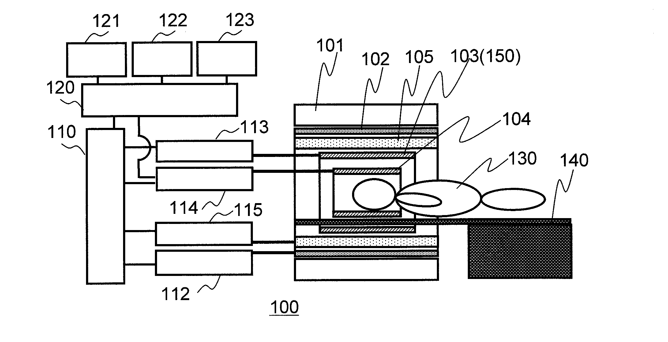
[0035]FIG. 1 is a block diagram showing a typical configuration of the magnetic resonance imaging (MRI) apparatus 100 according to the present embodiment. This MRI device is provided with a magnet 101, a gradient coil 102, a transmit RF coil (transmission coil) 103, a receive RF coil (reception coil) 104, a sequencer 110, a gradient power supply 112, an RF pulse generator 113, a receiver 114, an information processor 120, a storage unit 121, a display unit 122, an input unit 123, and a bed 140. In addition, if it is necessary to adjust homogeneity of the static magnetic field, a shim coil 105 and a ...

second embodiment

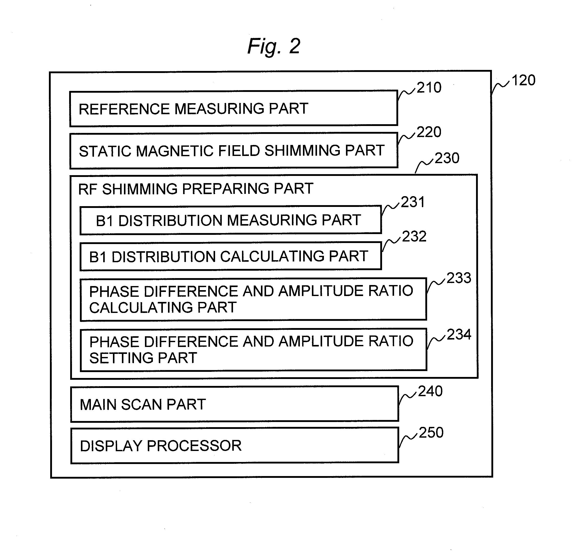
[0087]Next, an explanation will be made as to a second embodiment to which the present invention is applied. The MRI apparatus of the present embodiment has basically the same configuration as the MRI apparatus of the first embodiment. In the present embodiment, when the RF shimming preparing part calculates the B1 distribution, a division process is performed in addition to the subtraction process. Hereinafter, with regard to the present embodiment, an explanation will be made focusing attention on the RF shimming preparation process performed by the RF shimming preparing part, which is different from that of the first embodiment. Similar to the first embodiment, the RF shimming preparing part 230 of the present embodiment is also provided with the B1 distribution measuring part 231, the B1 distribution calculating part 232, the phase difference and amplitude ratio calculating part 233, and the phase difference and amplitude ratio setting part 234.

[0088]The B1 distribution measurem...


PUM


Abstract

B1 distribution is calculated in a short time with a high degree of precision, and a high quality image is obtained. In the RF shimming for irradiating electromagnetic waves using an RF coil having multiple channels, the absolute values of subtraction images between multiple reconstructed images are used to calculate a transmitting sensitivity distribution which is necessary for calculating inter-channel phase difference and amplitude ratio of RF pulses provided to the respective channels. Those multiple reconstructed images are obtained by executing the imaging sequence after applying a prepulse at different flip angles respectively. Assuming an image obtained with a minimum flip angle as a reference image, for instance, the subtraction images are created between the reference image and the other respective images. It is also possible that multiple subtraction images being obtained are divided by one another, and the transmitting sensitivity distribution is created on the basis of the division result.

Description

TECHNICAL FIELD[0001]The present invention relates to a magnetic resonance imaging apparatus (hereinafter, referred to as “MRI apparatus”), and more particularly, it relates to a technique for calculating a transmitting sensitivity distribution, the technique being used in RF shimming to reduce inhomogeneity of transmitting sensitivity in a transmit RF coil.BACKGROUND ART[0002]The MRI apparatus is a diagnostic imaging apparatus for medical use, utilizing nuclear magnetic resonance phenomenon due mainly to atomic nuclei of hydrogen. In general, a radio frequency magnetic field with a specific frequency is applied to a subject placed in a static magnetic field, simultaneously with a slice gradient magnetic field, thereby exciting nuclear magnetization within a cross section targeted for imaging. Next, a phase encoding gradient magnetic field and a readout gradient magnetic field are applied to provide the nuclear magnetization being excited with planar positional information, and a nu...

Claims


Application Information

Patent Timeline
IPC IPC(8): G01R33/341G01R33/54
CPCA61B5/055G01R33/5612G01R33/246G01R33/341G01R33/54G01R33/5659
Inventor YOKOSAWA, SUGURUTANIGUCHI, YOBITO, YOSHITAKAKANEKO, YUKIO
Owner FUJIFILM HEALTHCARE CORP
Why Eureka
Try Eureka