Implantable valvular prosthesis

a valvular prosthesis and implantable technology, applied in the field of medical devices, can solve the problems of incompetence or damage of the valve, disorder that is potentially life-threatening, and leakage of incompetent or damaged venous valves

Active Publication Date: 2005-05-05
CARDINAL HEALTH SWITZERLAND 515 GMBH
View PDF83 Cites 424 Cited by
  • Summary
  • Abstract
  • Description
  • Claims
  • Application Information

AI Technical Summary

Problems solved by technology

These valves can become incompetent or damaged by disease, for example, phlebitis, injury, or the result of an inherited malformation.
These disorder are potentially life threatening.
Similarly, incompetent or damaged venous valves usually leak, allowing the blood to improperly flow back down through veins away from the heart (regurgitation reflux or retrograde blood flow).
This stagnation of blood raises blood pressure and dilates the veins and venous valves.
The dilation of one vein may in turn disrupt the proper function of other venous valves in a cascading manner, leading to chronic venous insufficiency.
However, these treatments tend to be somewhat expensive and are not curative.
However, these surgical procedures provide somewhat limited results.
The leaflets of some venous valves are generally thin, and once the valve becomes incompetent or destroyed, any repair provides only marginal relief.
Currently, however, there are no effective drug therapies available.
These means have all had somewhat limited results.

Method used


Image

  • Implantable valvular prosthesis
  • Implantable valvular prosthesis
  • Implantable valvular prosthesis

Examples


Embodiment Construction

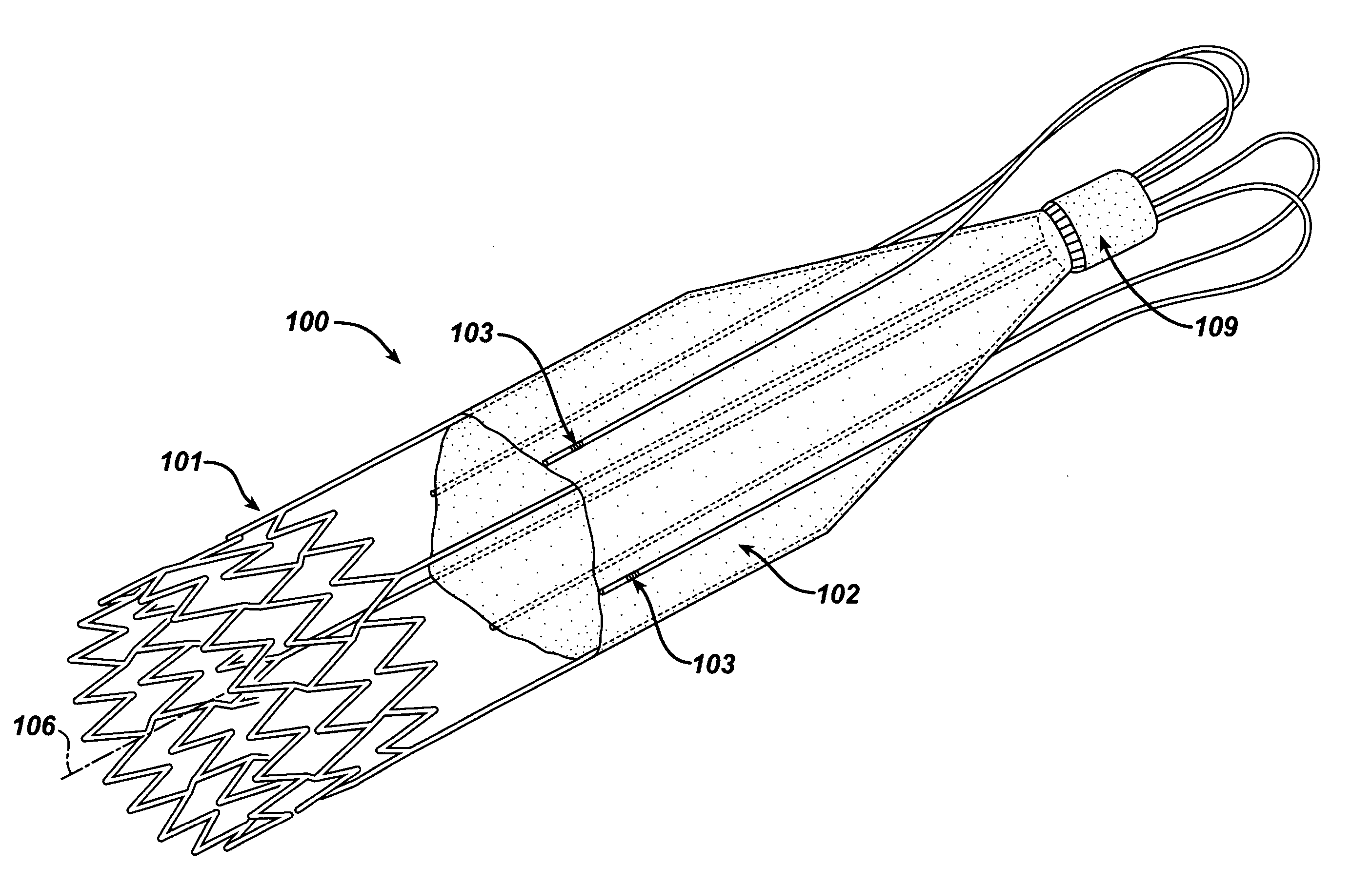
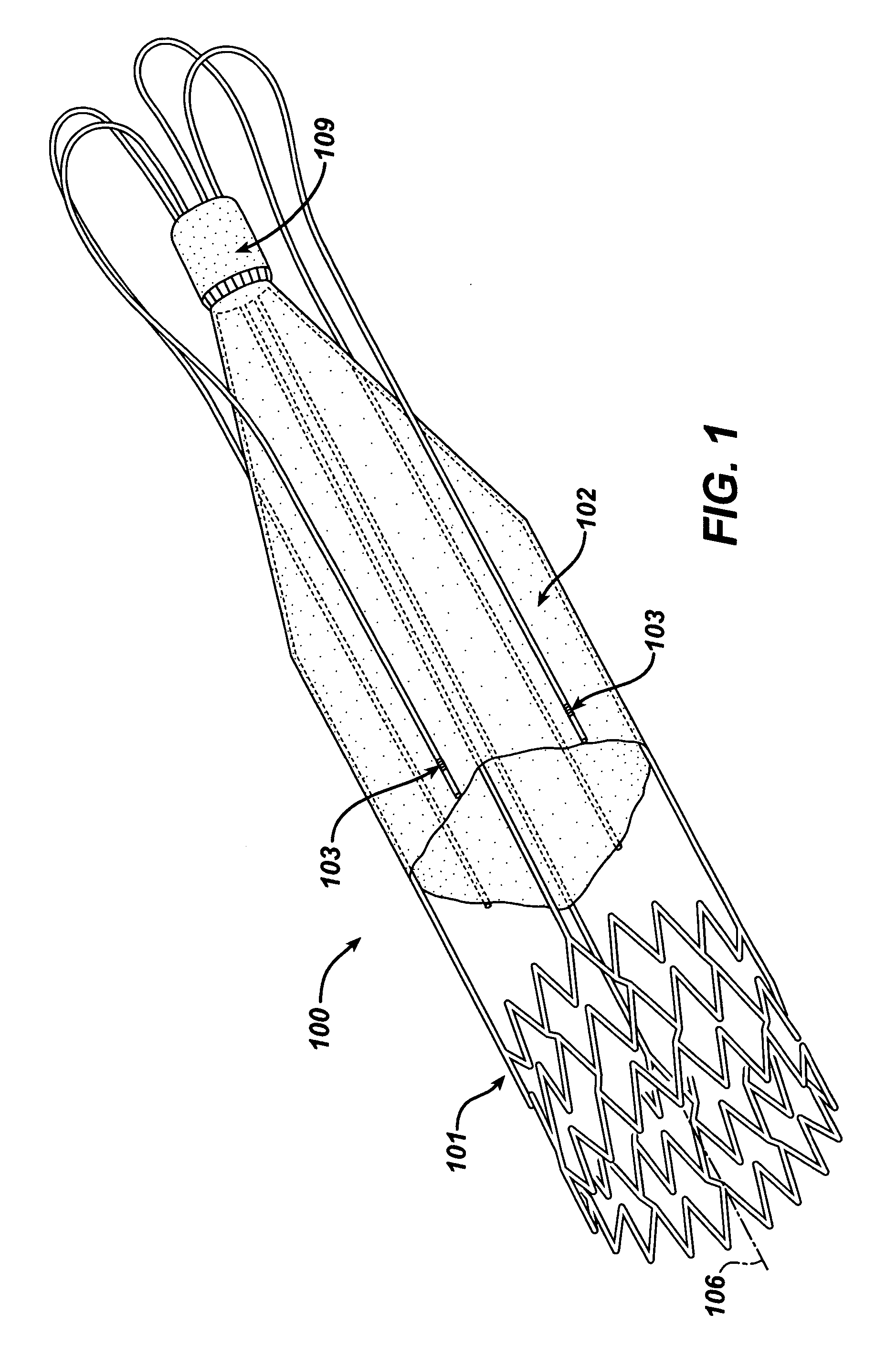
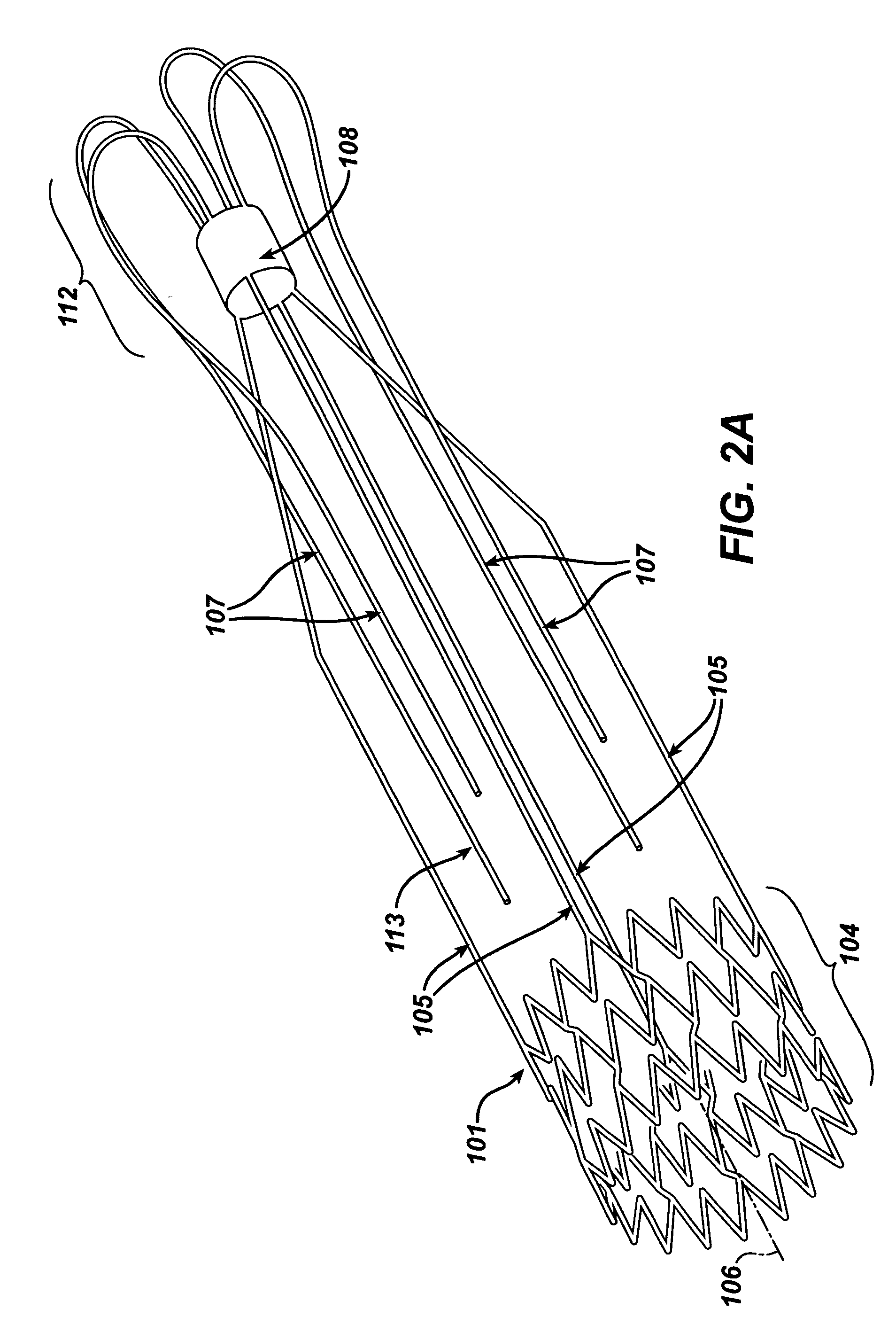
[0031] The stent-based valves of the present invention provide a method for overcoming the difficulties associated with the treatment of valve insufficiency. Although stent based venous valves are disclosed to illustrate one embodiment of the present invention, one of ordinary skill in the art would understand that the disclosed invention can be equally applied to other locations and lumens in the body, such as, for example, coronary, vascular, non-vascular and peripheral vessels, ducts, and the like, including but not limited to cardiac valves, venous valves valves in the esophagus and at the stomach, valves, in the ureter and / or the vesica, valves in the biliary passages, valves in the lymphatic system and valves in the intestines.

[0032] In accordance with one aspect of the present invention, the prosthetic valve is designed to be percutaneously delivered through a body lumen to a target site by a delivery catheter. The target site may be, for example, a location in the venous sy...


PUM


Abstract

The present invention relates to a medical device, and in particular, to a stent-based valve. The valve includes a radially expandable structural frame including an anchor structure having a first and a second open end, a connecting member having a first and a second end, and a cantilever valve strut having a first and a second end. The first end of the connecting member is attached to the second end of the anchor structure. The first end of the cantilever valve strut is cooperatively associated with the second end of the connecting member. The prosthetic valve further includes a biocompatible membrane assembly having a substantially tubular configuration disposed longitudinally about at least a portion of the connecting member. The membrane assembly has a first end having a first diameter and a second end having a second diameter, wherein the first diameter is greater than the second diameter. The first end of the membrane assembly is attached along the second end of the cantilever valve strut.

Description

FIELD OF THE INVENTION [0001] The present invention relates to a medical device, and more particularly to a frame based unidirectional flow prosthetic valve, and the method for fabricating such valve. BACKGROUND OF RELATED ART [0002] The human body has numerous biological valves that control fluid flow through body lumens and vessels. For example the circulatory system has various heart valves that allow the heart to act as a pump by controlling the flow of blood through the heart chambers, veins, and aorta. In addition, the venous system has numerous venous valves that help control the flow of blood back to the heart, particularly from the lower extremities. [0003] These valves can become incompetent or damaged by disease, for example, phlebitis, injury, or the result of an inherited malformation. Heart valves are subject to disorders, such as mitral stenosis, mitral regurgitation, aortic stenosis, aortic regurgitation, mitral: valve prolapse and tricuspid stenosis. These disorder ...

Claims


Application Information

Patent Timeline
Patent Type & Authority Applications(United States)
IPC IPC(8): A61F2/06A61F2/24A61F2/90
CPCA61F2/2418A61F2230/0054A61F2220/0016A61F2/2475
Inventor MAJERCAK, DAVID CHRISTOPHERHOJEIBANE, HIKMAT
Owner CARDINAL HEALTH SWITZERLAND 515 GMBH
Why Eureka
Try Eureka