
Integrated control apparatus for vehicle

a technology of integrated control apparatus and vehicle, which is applied in the direction of electric controllers, tractors, instruments, etc., can solve the problems of pneumatic trail en and the decrease of self-aligning torque tsa, and achieve the effect of improving vehicle stability and accurately determining the tire condition of all the wheels

Inactive Publication Date: 2005-05-05
JTEKT CORP
View PDF9 Cites 39 Cited by
  • Summary
  • Abstract
  • Description
  • Claims
  • Application Information

AI Technical Summary

Benefits of technology

[0013] In view of the foregoing, an object of the present invention is to provide an integrated control apparatus for a vehicle having independently steerable wheels, which apparatus can estimate exact grip factors of the individual wheels, and which can integrally control actuators of at least two of a steering system, a brake system, and a drive system, by optimally distributing a control quantity in accordance with the grip factor of each wheel, to thereby improve the stability of the vehicle.
[0022] Since the present invention is applied to a vehicle having wheels, all of which are independently steerable, the tire conditions of all the wheels can be determined accurately. Moreover, under the present invention, the grip factors of the wheels are estimated individually in such a vehicle having independently steerable wheels. Therefore, the respective actuators of at least two systems among the brake system, the drive system, and the steering system can be integrally controlled at an optimal distribution ratio determined on the basis of the grip factors of the wheels, whereby the stability of the vehicle can be improved.

Problems solved by technology

However, when the lateral grip of the tire is lost, and the slip region increase, the pneumatic trail en and the self-aligning torque Tsa decrease.

Method used


Image

  • Integrated control apparatus for vehicle
  • Integrated control apparatus for vehicle
  • Integrated control apparatus for vehicle

Examples


Embodiment Construction

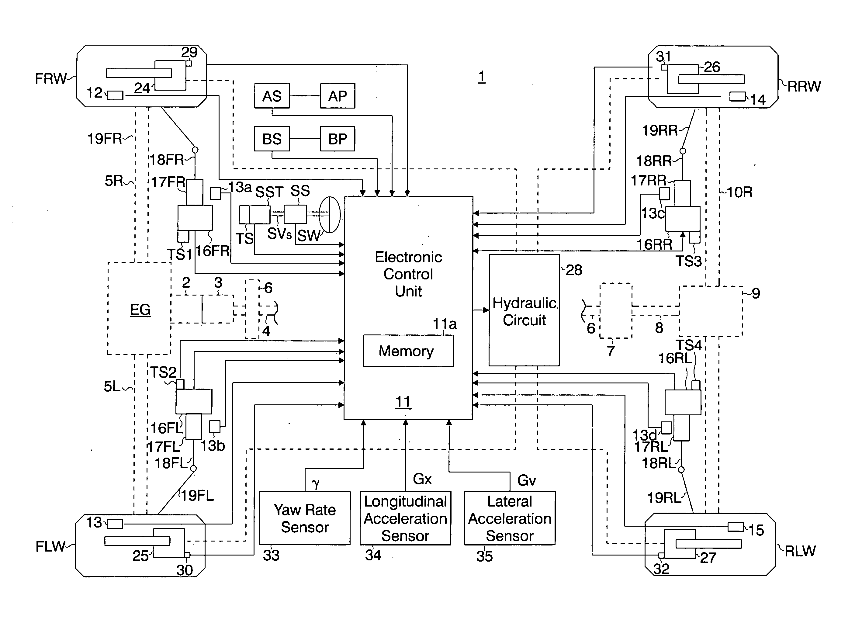
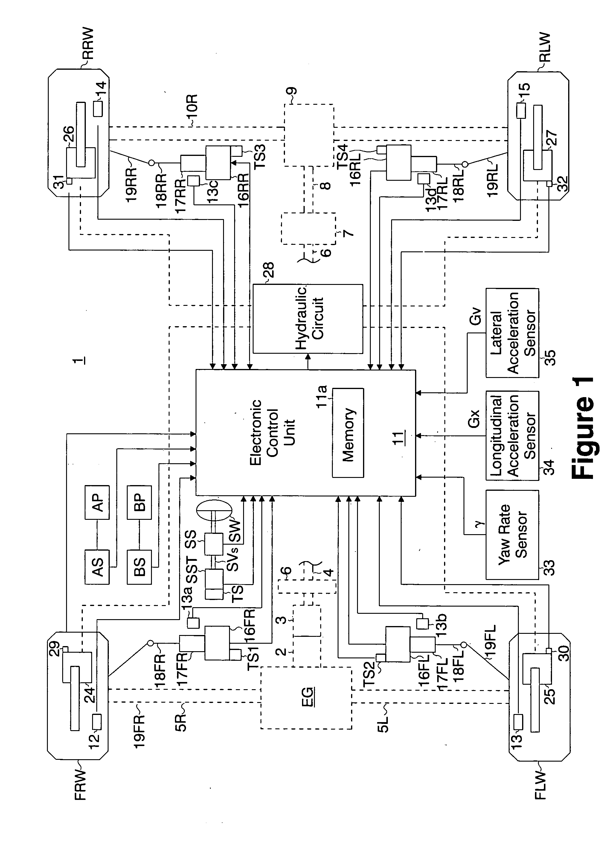
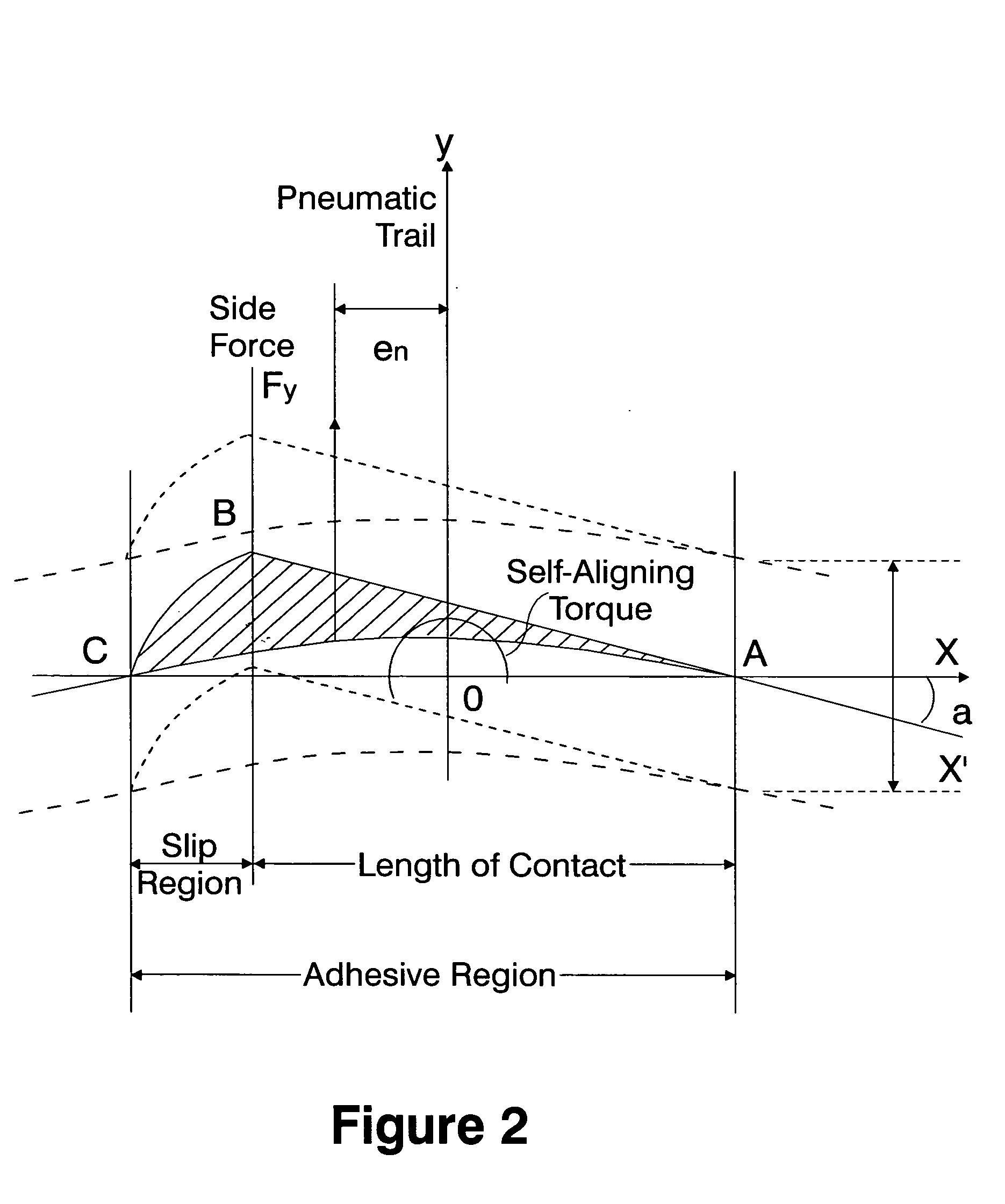
[0041] An embodiment of the present invention will next be described with reference to FIGS. 1 to 9. FIG. 1 is a schematic configuration view of an integrated control apparatus for a vehicle according to the present embodiment. FIG. 2 is a graph showing the relation between self-aligning torque and side force in an ordinary vehicle whose tires are rolling while skidding. FIG. 3 is a simplified representation of the situation depicted in FIG. 2 showing the relation between self-aligning torque and side force. FIG. 4 is a block diagram of an electronic control unit 11. FIG. 5 is a block diagram of a grip factor calculation section 41. FIG. 6 is an explanatory view showing a 2-wheel vehicle model having a front wheel and a rear wheel. FIG. 7 is a control flowchart. FIG. 8 is a graph showing side force vs. self-aligning torque characteristics. FIG. 9 is a graph showing self-aligning torque vs. steering-mechanism friction component characteristics in relation to correction at the time of...


PUM


Abstract

In a vehicle of a four-wheel independent steering type, an electronic control unit calculates a target yaw rate in accordance with a vehicle speed and a steering angle, and calculates a vehicle-control target value on the basis of the target yaw rate and an actual yaw rate. The electronic control unit estimates the grip factors of the individual wheels to road surface, and sets a distribution ratio for distribution of the vehicle-control target value among actuators of a steering system, a brake system, and a drive system in accordance with the estimated grip factors. The electronic control unit controls the actuators of the three systems in accordance with control instruction values determined on the basis of the vehicle-control target value and the distribution ratio.

Description

INCORPORATION BY REFERENCE [0001] The present application claims priority under 35 U.S.C. §119 to Japanese Patent Application No. 2003-344744 filed on Oct. 2, 2003. The content of the application is incorporated herein by reference in its entirety. BACKGROUND OF THE INVENTION [0002] 1. Field of the Invention [0003] The present invention relates to a integrated control apparatus for a vehicle. [0004] 2. Description of the Related Art [0005] A tire grip factor differs from a lateral force utilization factor or a lateral G utilization factor disclosed in Japanese Laid-Open Patent Application No. H11-99956. Specifically, the apparatus disclosed in this publication obtains the maximum lateral force that can be generated on a road surface, from the frictional coefficient μ of the road surface. This road-surface frictional coefficient μ is estimated on the basis of the dependency of cornering power Cp (defined to be a value of side force at a slip angle of 1 degree) on the road-surface fri...

Claims


Application Information

Patent Timeline
IPC IPC(8): B60K23/08B60K28/16B60R16/02B60T8/172B60T8/1755B60T8/1763B60W10/00B60W10/12B60W10/18B60W10/188B60W10/20B60W40/068B60W40/10B62D5/04B62D6/00B62D7/14B62D7/15B62D103/00B62D111/00B62D113/00B62D119/00B62D137/00G05B11/01G05B15/02
CPCB60K23/0808B60K28/165B60T8/172B60T8/1755B60T2230/02B60W2520/26B60T2260/08B60W10/04B60W10/18B60W10/20B60W30/02B60T2260/022
Inventor OHTA, TAKAYUKIMOMIYAMA, MINEKAZUKATO, HIROAKIKODAMA, AKIRA
Owner JTEKT CORP
Features
  • Generate Ideas
  • Intellectual Property
  • Life Sciences
  • Materials
  • Tech Scout
  • Unparalleled Data Quality
  • Higher Quality Content
  • 60% Fewer Hallucinations
Learn More