Printing blanket construction and method of making

a printing blanket and construction method technology, applied in printing blankets, rotary lithographic machines, printing, etc., can solve the problems of premature blanket failure, swelling and delamination of the blanket layer, and the trailing end edges of the blanket being exposed, so as to reduce the shock effect (impact force), increase the surface area, and protect the

Active Publication Date: 2005-05-12
DAY INT
View PDF20 Cites 35 Cited by
  • Summary
  • Abstract
  • Description
  • Claims
  • Application Information

AI Technical Summary

Benefits of technology

[0019] By removing a portion of the leading edge of the blanket or molding the leading edge to have a desired shape, the gap between the leading and trailing edges is reduced, which is believed to reduce the shock effect (impact forces) which typically occurs with the use of conventional blankets when the blanket ends come into compressive interference at the nip between the blanket and print cylinders.
[0020] In embodiments where an optional sealant is adhered to at least one of the leading and trailing edges, modifying the leading edge increases the surface area of the leading edge such that the sealant adheres more readily to the blanket edge. The sealant provides effective protection and does not peel or split. Thus, the sealant effectively seals the leading...

Problems solved by technology

However, this type of narrow-gap lock-up system results in the leading and trailing end edges of the blanket being exposed rather than tucked inside the lock-up or cylinder.
This exposure subjects the blanket ends to mechanical impact forces and the penetration of water, inks and chemicals used during the printing process, which can result in swelling and delamination of the blanket layers.
Such conditions may cont...

Method used


Image

  • Printing blanket construction and method of making
  • Printing blanket construction and method of making
  • Printing blanket construction and method of making

Examples


Embodiment Construction

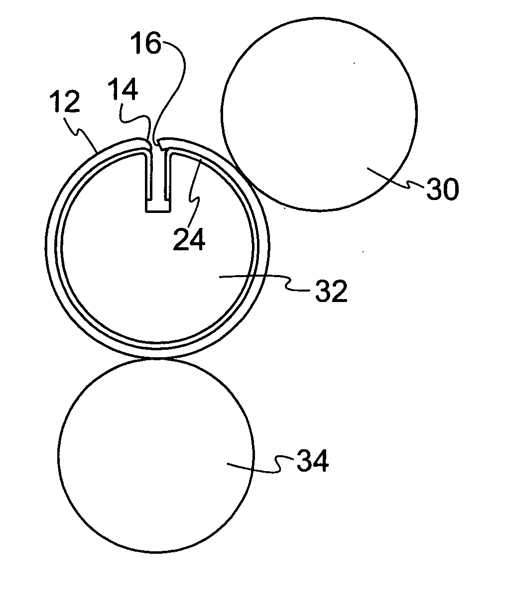
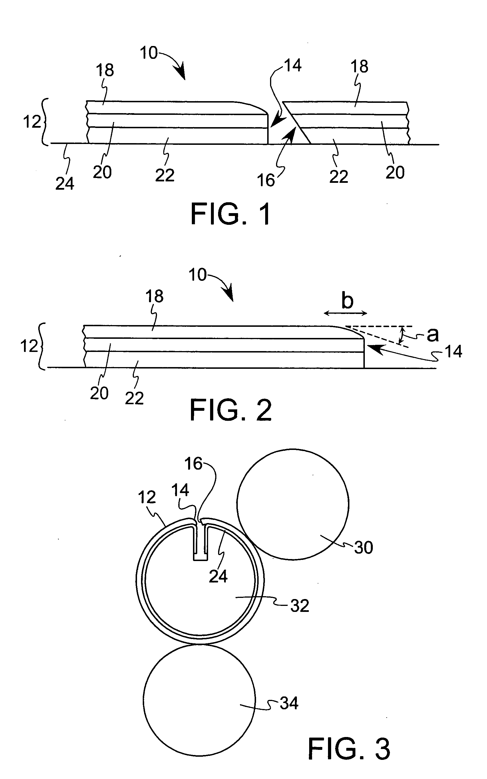
[0028]FIG. 1 illustrates one embodiment of the printing blanket construction of the present invention. The printing blanket construction 10 includes a printing blanket 12 having leading and trailing edges, 14 and 16, respectively. By “leading edge,” we mean that edge of the blanket which, when mounted on a rotating blanket cylinder, is the edge that first enters the nip between the blanket cylinder and printing cylinder. By “trailing edge,” we mean the edge of the blanket opposite the leading edge.

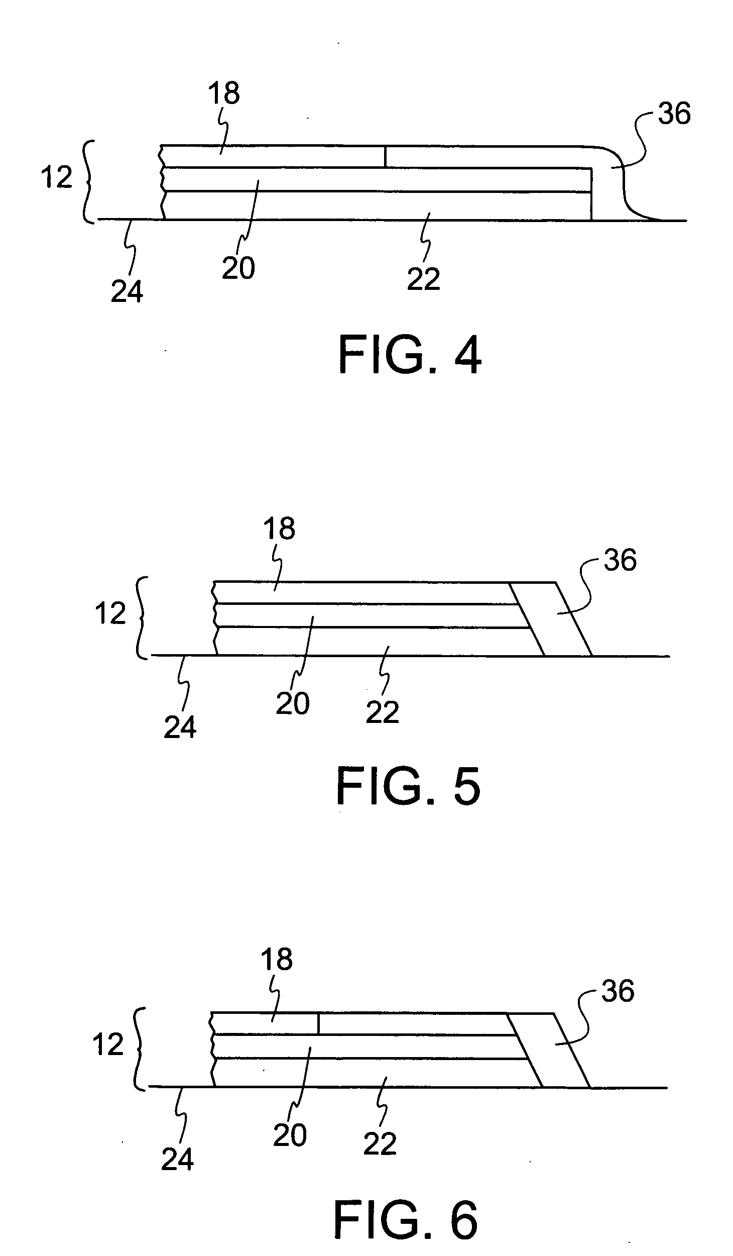
[0029] The blanket preferably includes a top ply 18, an intermediate ply 20, a bottom ply 22, and a non-extensible backing ply 24. The top ply 18 is preferably an inked image accepting surface ply. The intermediate and bottom plies may comprise compressible plies and / or reinforcing plies, depending on the design of the blanket. The leading and trailing edges of the blanket are secured directly to the backing ply as is conventional in the art. The non-extensible backing ply preferably comp...


PUM


Abstract

An improved printing blanket construction is provided which includes at least a top ply, a bottom ply, and a non-extensible backing ply. The blanket includes leading and trailing edges which are secured directly to the backing ply, where at least a portion of the leading edge forms a contoured edge, a stair-stepped edge, a beveled edge, or a combination thereof. The printing blanket construction having such a shaped leading edge reduces printing gap, reduces the impact forces on the leading edge of the blanket, and protects the blanket from the penetration of ink, solvents, moisture and the like into the blanket plies during use.

Description

CROSS REFERENCE TO RELATED APPLICATIONS [0001] This application claims the benefit of U.S. Provisional Application No. 60 / 518,783 filed Nov. 10, 2003.BACKGROUND OF THE INVENTION [0002] The present invention relates in general to a printing blanket construction, and more particularly, to an improved printing blanket which reduces printing gap, which reduces the impact forces on the leading edge of the blanket, and which prevents the penetration of ink, solvents, moisture and the like into the blanket plies during use. [0003] One of the most common commercial printing processes is offset lithography. Non-tensioned offset printing blankets are typically made on a thin, low elongation carrier, or backing, having ends that extend beyond the end of the actual printing blanket. The ends are bent or otherwise formed so that they can be inserted into a narrow-gap printing press cylinder lock-up to hold the blanket in place. [0004] However, this type of narrow-gap lock-up system results in th...

Claims


Application Information

Patent Timeline
IPC IPC(8): B41N10/04
CPCB41N10/04
Inventor FLINT, W. TORIRANCZERNER, RICHARD
Owner DAY INT
Why Eureka
Try Eureka