
Current powered vehicle

a current-powered vehicle and vehicle technology, applied in the direction of propulsion parts, transportation and packaging, propulsion power supply, etc., can solve the problems of increasing air pollution, increasing the cost of fossil fuels, and increasing the pollution of vehicles, so as to reduce the pollution of vehicles and reduce the emissions of vehicles

Inactive Publication Date: 2005-05-12
MITCHELL WALTER
View PDF17 Cites 32 Cited by
  • Summary
  • Abstract
  • Description
  • Claims
  • Application Information

AI Technical Summary

Benefits of technology

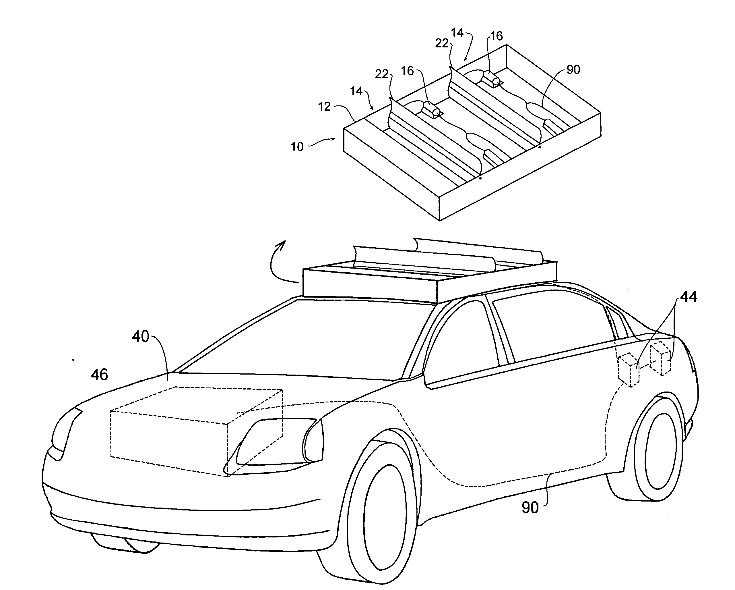
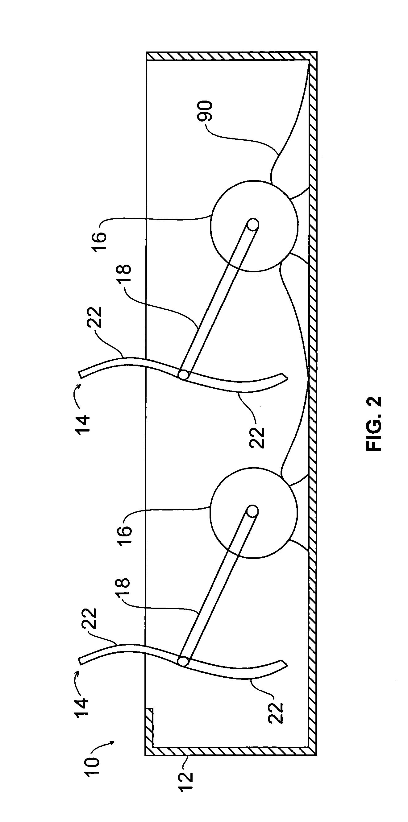
[0009] The present invention is an air- or water-power system that can charge or maintain the charge on a vehicle battery and that can provide electricity to operate an electric motor for running a vehicle. The power system provides a means for electricity generation while the vehicle is in motion by using either or both of the naturally occurring air or water currents and / or the relative air or water currents generated by the vehicle when in motion. Broad-bladed horizontal fan blades laterally extending across the vehicle are used to catch the current and to transfer the current's energy to electrical alternators. This electricity ultimately provides power to the vehicle as the electricity is provided directly to the electric motor that powers the vehicle, or is provided to charge the batteries, which are connected to the motor that powers the vehicle. The power system is used to convert mechanical airflow or waterflow energy into electrical energy to power the useful features of the vehicle and / or to supplement the power supply for the vehicle. As such, the power system can be used to improve the efficiency of an array of vehicles, including electric-powered vehicles, hybrid electric and gasoline-powered vehicles, and gasoline-powered vehicles.
[0011] Preferably, there are two or more fan units positioned one behind the other on the vehicle, or at some other relatively open location proximal to the air or water currents. For a land or air vehicle, a suitable location is on the top of the vehicle. For a water vehicle, a suitable location for an airflow embodiment is on the top of the vehicle and a suitable location for a waterflow embodiment is on the vehicle below the water line. Although the two fan units can lie in the same horizontal plane, the rear fan unit can be positioned above the fore fan unit so as to form a wedge-like configuration. More specifically, in the airflow embodiment, the second of the two fan units is arranged higher from roof than the first of the two fan units. Preferably, the wedge faces the front of the vehicle, as this configuration is more efficient in harvesting the currents. Specifically, this configuration is advantageous in that it provides for a more aerodynamic and hydrodynamic shape to the power system and as such is able to lower the added drag force of the power system on the vehicle. If three or more fan units are used, this wedge configuration can be continued relative to the third and rearmost fan unit.
[0014] Another feature of the present invention is that it can allow a vehicle to run without the use of carbon-based fuels, thereby decreasing the pollution emitted from the vehicle. By incorporating such an invention into a vehicle, it may be possible to reduce the emissions of a vehicle without comprising the general performance of the vehicle.

Problems solved by technology

Over the past century, air pollution has become an ever-increasing problem, especially in the area around and in large cities.
The greenhouse gases and other poisons that are created by gasoline-driven and other fossil fuel-powered vehicles pose a serious threat to the life expectancy of humans, other living inhabitants of the Earth, and even the Earth itself.
The availability and cost of fossil fuels is in constant flux.
Further, although gasoline stations are relatively ubiquitous, especially in the United States, there still are locations where gasoline is not available, including in the air for flying vehicles and on bodies of water for floating vehicles.
Various attempts to reduce or eliminate the air pollution problem associated with the noxious and poisonous fumes emanating from gasoline-powered vehicles have not been completely successful.
While the concept of electric vehicles, such as electric and electric / gasoline hybrid automobiles, has been known for decades, the method or system for providing power to run such vehicles or to at least charging the batteries of such vehicles has been elusive.
The size limitation and the limited electrical capacities of the batteries also have severely limited the cruising range of such vehicles.

Method used


Image

  • Current powered vehicle
  • Current powered vehicle
  • Current powered vehicle

Examples


Embodiment Construction

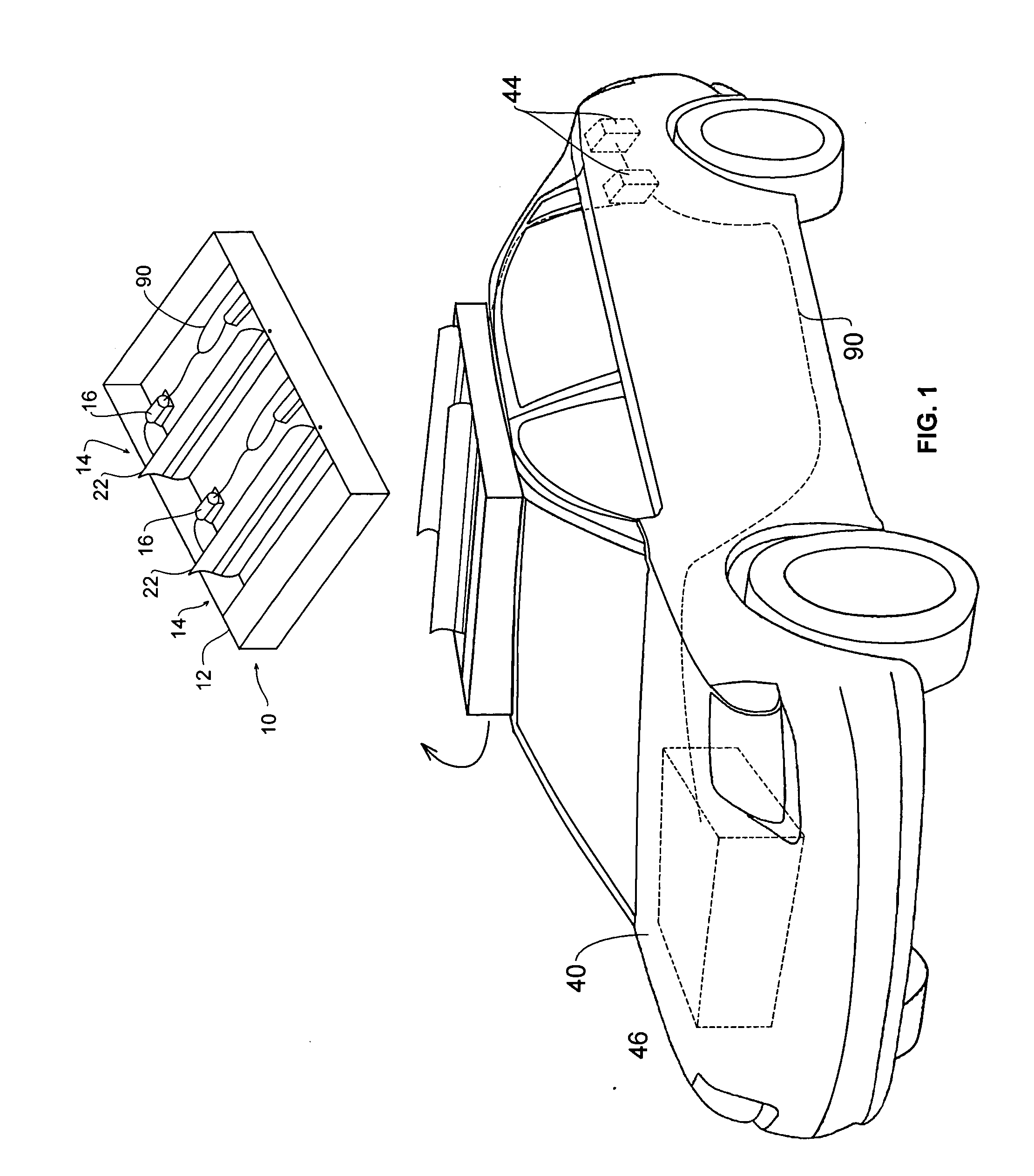
[0031] Illustrative embodiments of the power system and its components and placement on an example vehicle according to the present invention are shown in FIGS. 1 through 15. Although vehicle 40 as shown in the figures is an automobile, watercraft or train, it is understood that power system 10 may be used or installed on any vehicle, including trucks, trailers, aircraft and the like. Further, while power system 10 primarily is shown to be on the top or roof of vehicle 40, it is understood that power system, or various components thereof such as fan units 14 can be on the sides of vehicle 40. While the invention is described herein in conjunction with the exemplary and preferred embodiments, it will be understood that the invention is not limited to these embodiments.

[0032] Referring now to FIG. 1, a perspective view of one embodiment of the invention is shown installed on a landcraft. Vehicle 40 has a conventional electrically powered, a hybrid electrically / gasoline powered, or ot...


PUM


Abstract

A power system for powering a vehicle having an airflow or waterflow channeling device mounted on the vehicle, a laterally mounted fan unit, and an electric alternator connected to the fan unit, in which airflow or waterflow spins the laterally mounted fan thus generating electricity via the electric alternator to power the vehicle.

Description

BACKGROUND OF THE INVENTION [0001] 1. Technical Field [0002] The present invention generally is related to devices for powering vehicles such as automobiles, trucks, boats, trains, airplanes or other vehicles, and more particularly is related to device for using air or water current to power a vehicle and produce vehicle movement through the use of fan blades, turbine blades, squirrel cage fans and the like attached to an electric alternator for producing electricity to power an electric motor for powering the vehicle. [0003] 2. Prior Art [0004] Over the past century, air pollution has become an ever-increasing problem, especially in the area around and in large cities. The greenhouse gases and other poisons that are created by gasoline-driven and other fossil fuel-powered vehicles pose a serious threat to the life expectancy of humans, other living inhabitants of the Earth, and even the Earth itself. The automobile and other vehicles are considered major factors in creating this pr...

Claims


Application Information

Patent Timeline
IPC IPC(8): B60L8/00
CPCY02T10/7083B60L2200/26B60L8/006Y02T10/7072
Inventor MITCHELL, WALTER
Owner MITCHELL WALTER
Learn More