
Fuel injector

Inactive Publication Date: 2005-05-12
HITACHI LTD
View PDF7 Cites 34 Cited by
  • Summary
  • Abstract
  • Description
  • Claims
  • Application Information

AI Technical Summary

Benefits of technology

[0011] An object of the present invention is to provide a fuel injection valve that there are very few product variations, and the problem due to the thermal expansion is solved, and the measurement accuracy and reliability are high.
[0030] The present invention provides a fuel injection valve that there are very few product variations, and the problem due to the thermal expansion is solved, and the measurement accuracy and reliability are high.

Problems solved by technology

However, as described in Japanese Laid-open Patent Publication 9-310654, in the inward opening type fuel injection valve using a magneto-striction element, the following problem is imposed.
Namely, the magneto-striction element is a material that the dimensional accuracy at the time of processing is hardly obtained, so that a problem arises that dimensional variations are large.
However, one end of the element is fixed to the main unit case via the element holder, so that variations in the processing dimensions of the element adversely affect straight the dimensions of the gap and a problem arises that only by the element and element holder, dimensional variations cannot be adjusted.
This elongation change is more than the request stroke (generally in the order of several tens μm) of the injection valve, so that not only precise control of the fuel injection amount cannot be executed due to the thermal expansion of the element but also according to circumstances, a problem arises that the function of the injection valve is lost.

Method used


Image

  • Fuel injector
  • Fuel injector
  • Fuel injector

Examples


Embodiment Construction

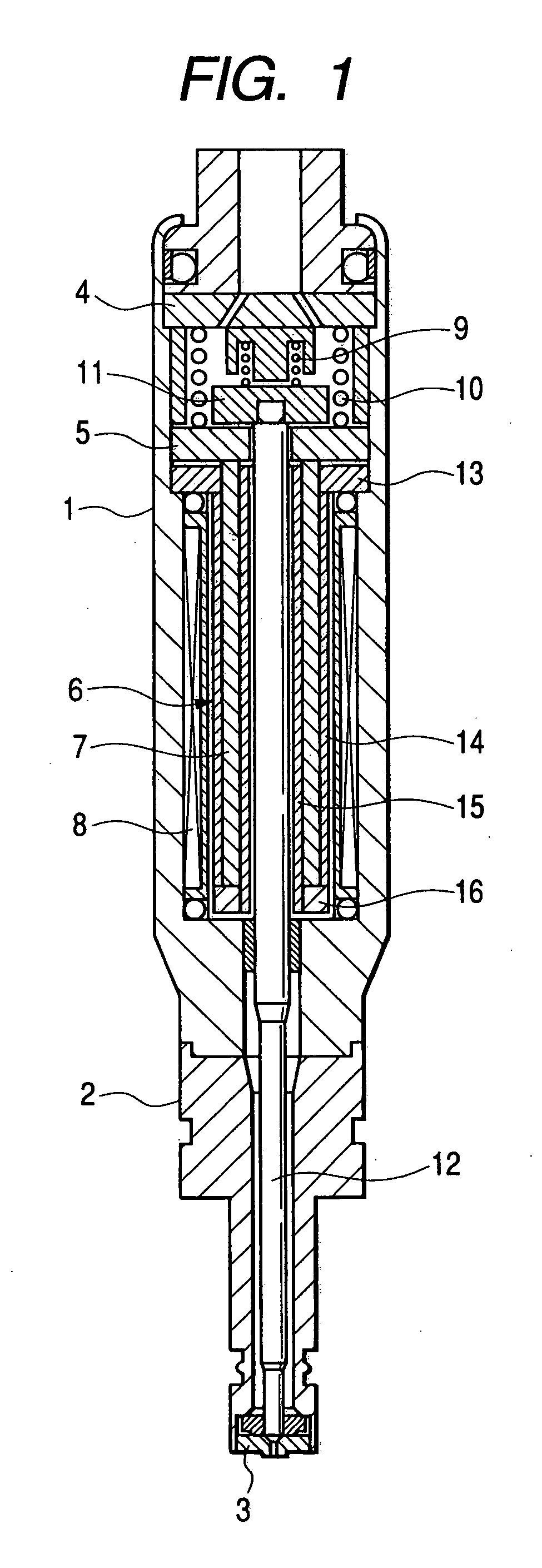
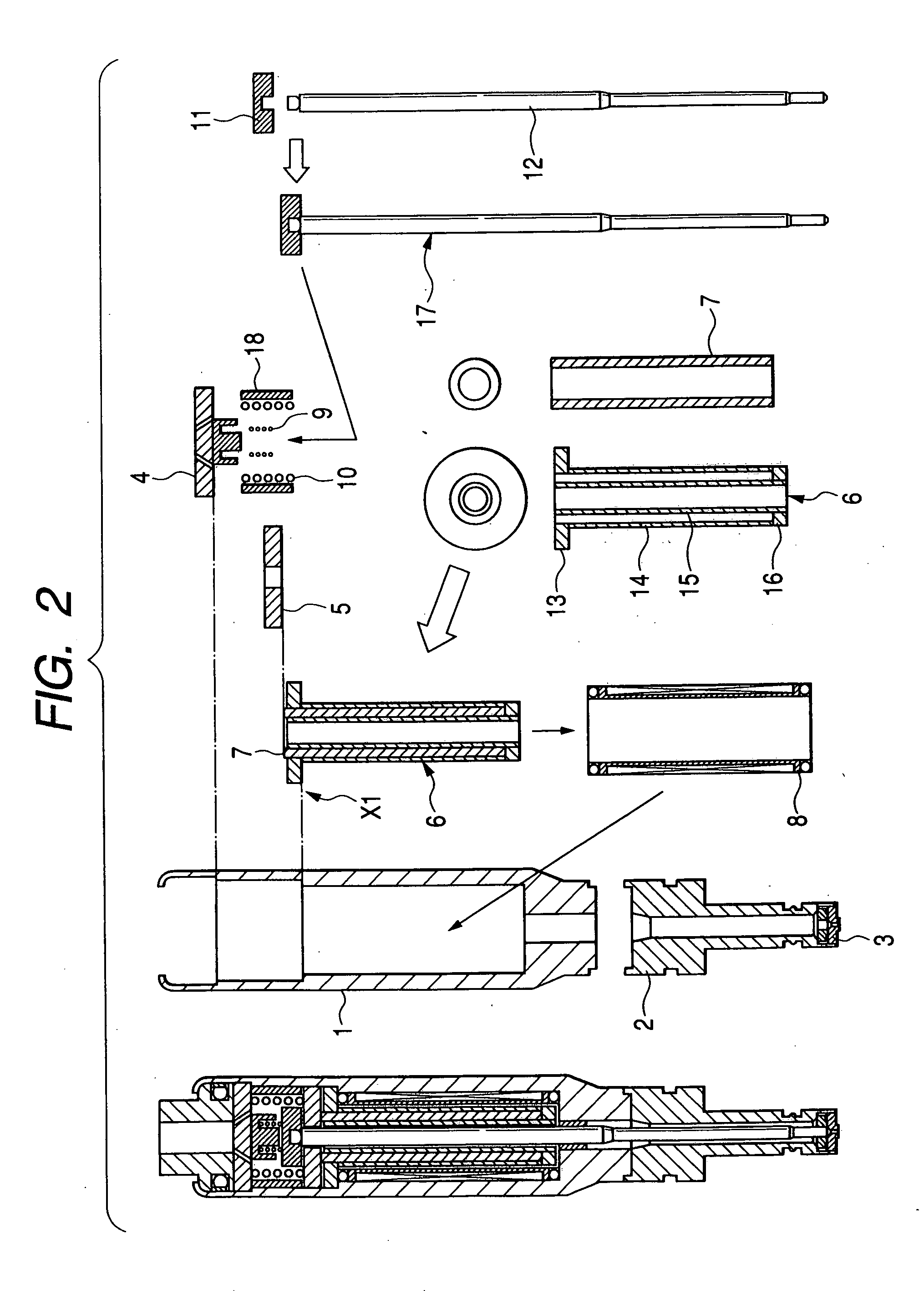
[0035] The constitution of the fuel injection valve of an embodiment of the present invention will be explained below with reference to FIGS. 1 to 3.

[0036] Firstly, by referring to FIGS. 1 and 2, the whole constitution of the fuel injection valve of this embodiment will be explained.

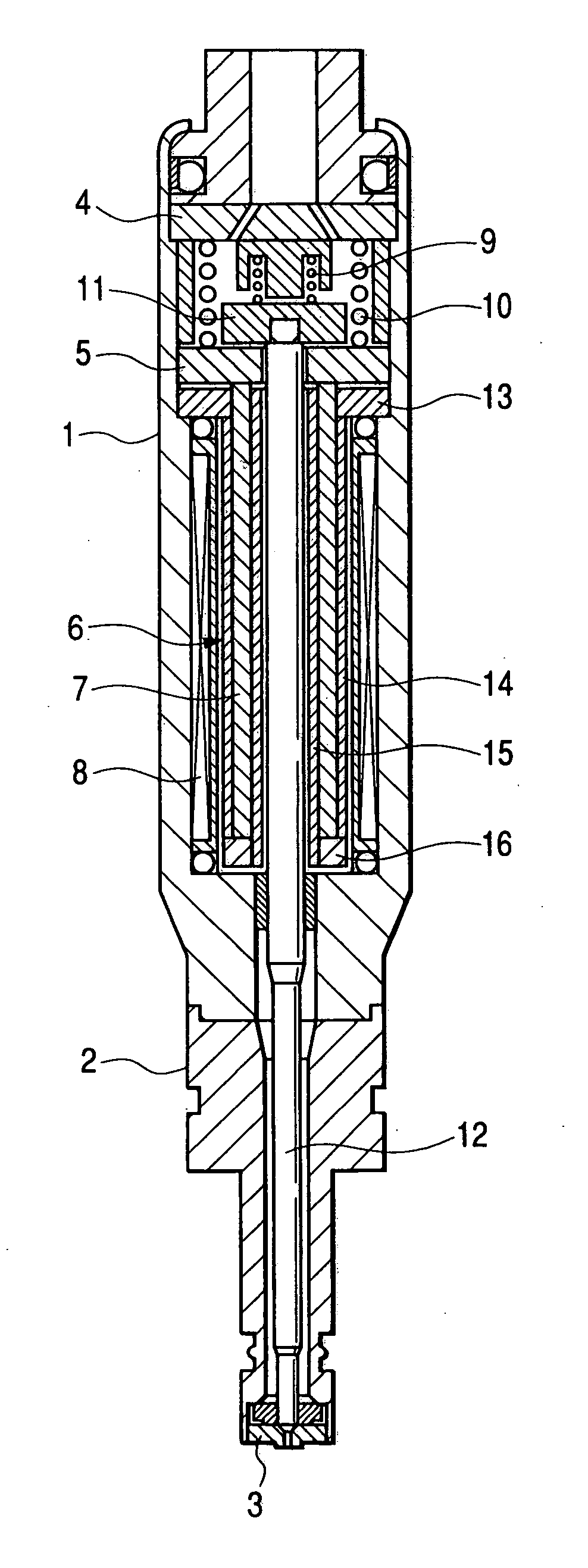
[0037]FIG. 1 is a cross sectional view showing the whole constitution of the fuel injection valve of an embodiment of the present invention. FIG. 2 is an assembly drawing of the fuel injection valve of an embodiment of the present invention. In FIGS. 1 and 2, the same numerals indicate the same parts.

[0038] Hereinafter, mainly, by referring to FIG. 2, the constitution of the fuel injection valve of this embodiment will be explained. A nozzle sheet 3 is fit into the front end of a nozzle body 2. In the nozzle sheet 3, a nozzle is formed and the shape thereof is the same as the conventional one. The shape of the front end of a plunger rod 12 in contact with the nozzle sheet 3 is the same as the conventi...


PUM


Abstract

A magneto-striction element 7 is inserted and held by an element holder assembly 6. A flange 13 at the upper end of the element holder assembly 6 is positioned on a main unit case 1 of the fuel injection valve 6 as a fixed end and the lower end of the element holder assembly 6 is set as a free end which can expand and contract vertically. An inward opening specification is used that when the magneto-striction element 7 expands, the plunger 13 is pulled upward in the injection valve in the opposite direction of the combustion chamber side and from the gap between a nozzle sheet 3 arranged on the combustion chamber side and the front end of the plunger 13, fuel is injected.

Description

CLAIM OF PRIORITY [0001] The present application claims priority from Japanese application serial No. 2003-345261, filed on Oct. 3, 2003, the content of which is hereby incorporated by reference into this application. BACKGROUND OF THE INVENTION [0002] The present invention relates to a fuel injector of an inward opening type using a magneto-striction element suitable for an internal combustion engine. [0003] An internal combustion engine for a car requires an advanced mixed gas forming art of injected fuel and air and a highly precise fuel injection art. To execute precise control for the fuel injection rate, a high degree of response is required for a fuel injection valve. [0004] As a method for realizing it, for the drive system of the injection valve, in place of the conventional solenoid electromagnetic drive method, a one using a magneto-striction element has been developed. With respect to the fuel injection valve using a magneto-striction element, the outward opening type an...

Claims


Application Information

Patent Timeline
IPC IPC(8): F02M51/06F02M61/16F02M63/00
CPCF02M51/0607F02M61/168F02M61/167F02M61/161
Inventor ISHII, MITSUNORI
Owner HITACHI LTD
Learn More