
Drive control method, drive control device, belt apparatus, image forming apparatus, image reading apparatus, computer product

a technology of drive control and control device, which is applied in the direction of program control, electronic commutator, instruments, etc., can solve the problems of incorrect reading, wrong position control, and wrong position control

Inactive Publication Date: 2005-05-12
RICOH KK
View PDF43 Cites 55 Cited by
  • Summary
  • Abstract
  • Description
  • Claims
  • Application Information

AI Technical Summary

Benefits of technology

[0016] A drive control method according to an aspect of the present invention is a method of controlling driving of a pulse motor such that a rotating body driven by the pulse motor rotates at uniform angular velocity. The drive control method includes detecting angular displacement of the rotating body; calculating a difference between a detection value of the angular displacement and a target value of angular displacement set in advance; and calculating a drive pulse frequency of a drive pulse signal to be used for driving for the pulse motor based on the difference and a reference drive pulse frequency to make it possible to select whether the difference is added to the reference drive pulse.
[0018] A drive control device according to still another aspect of the present invention is a device that controls driving of a pulse motor such that a rotating body driven by the pulse motor rotates at uniform angular velocity. The drive control device includes an angular displacement detecting unit that detects angular displacement of the rotating body; a difference calculating unit that calculates a difference between a detection value of the angular displacement and a target value of angular displacement set in advance; and a drive pulse frequency calculating unit that calculates a drive pulse frequency of a drive pulse signal to be used for driving for the pulse motor based on the difference and a reference drive pulse frequency to make it possible to select whether the difference is added to the reference drive pulse.
[0019] A drive control device according to still another aspect of the present invention is a device that controls driving of a pulse motor such that a moving body driven by the pulse motor moves at a uniform velocity. The drive control device includes a difference calculating unit that calculates a difference between a detection value of displacement of the moving body and a target value of displacement set in advance; a drive pulse frequency calculating unit that calculates a drive pulse frequency of a drive pulse signal to be used for driving for the pulse motor based on the difference and a reference drive pulse frequency; and a selecting unit that makes it possible to select whether the difference is added to the reference drive pulse.

Problems solved by technology

However, in the conventional technology, eccentricity of the shaft to which the encoder is attached, eccentricity of an attachment position of the encoder with respect to the shaft, and the like causes wrong position control.
However, the scale may become damaged during operation and may produce incorrect readings which leads to incorrect position control.
Moreover, there is always a distinct boundary (hereinafter, “joint”) between the rotating body and the scale, which also produces incorrect readings.
However, eccentricity of the drive shaft, errors in the positions of the reference marks, and the like produces incorrect detection and results in inaccurate feedback control.
However, this drive system has a drawback in that, for example, when a detector breaks down or, in particular, when there is a wrong output in a detection signal in, for example, a joint part of a scale at the time when a surface displacement sensor is used, accurate control cannot be performed.
However, with only a velocity control system, it is impossible to cope with a highly accurate position control system.
This causes an increase in cost due to an increase in the number of components.
However, two or more sensors are required in this method, and an increase in cost is also unavoidable.
Thus, an increase in cost by an increase in the number of sensors is unavoidable.
In addition, when abnormality has occurs with time in an optical pattern (scale) that is a detection object, the number of sensors is meaningless, and suspension and the like of an apparatus operation are unavoidable.

Method used


Image

  • Drive control method, drive control device, belt apparatus, image forming apparatus, image reading apparatus, computer product
  • Drive control method, drive control device, belt apparatus, image forming apparatus, image reading apparatus, computer product
  • Drive control method, drive control device, belt apparatus, image forming apparatus, image reading apparatus, computer product

Examples


first embodiment

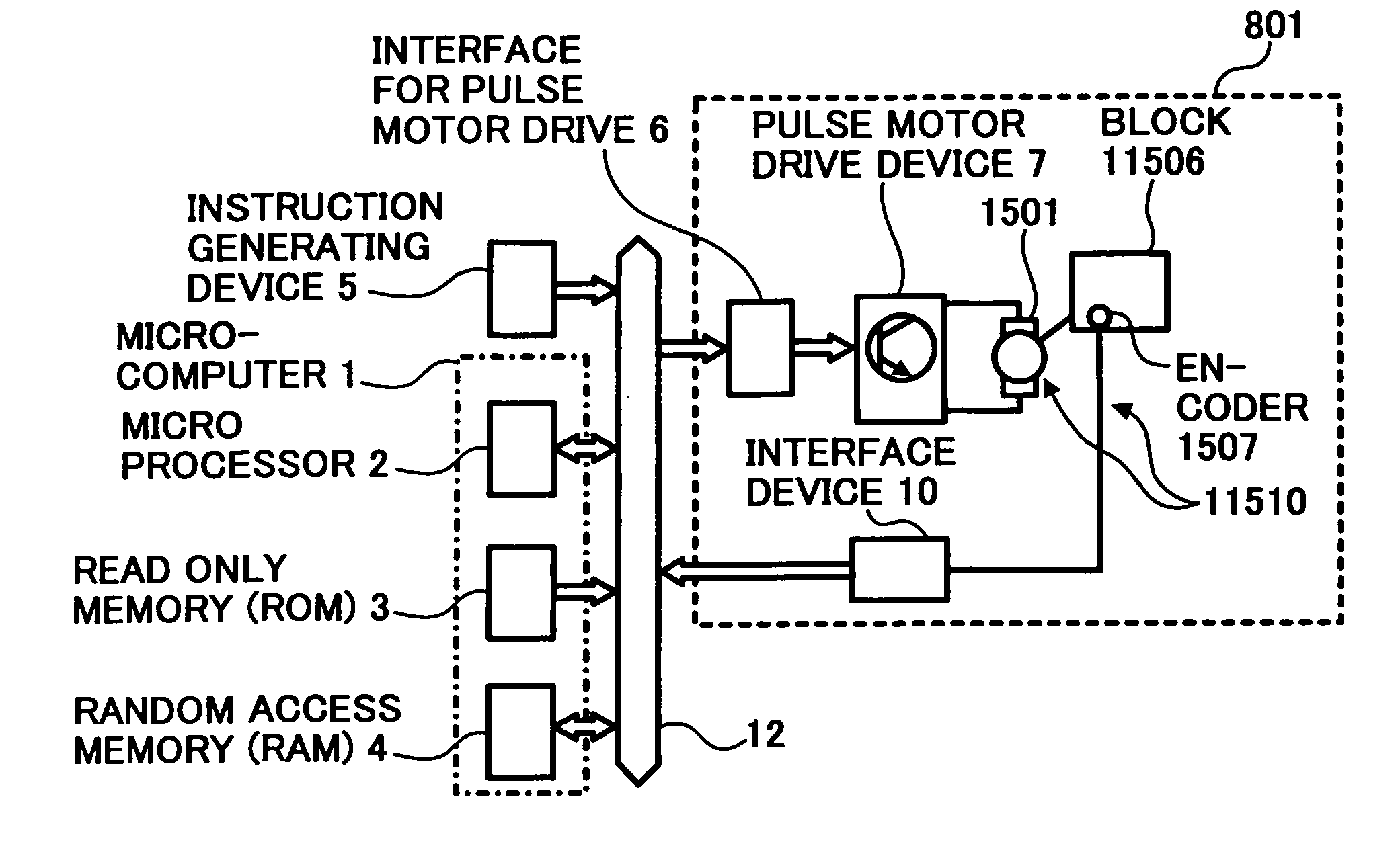
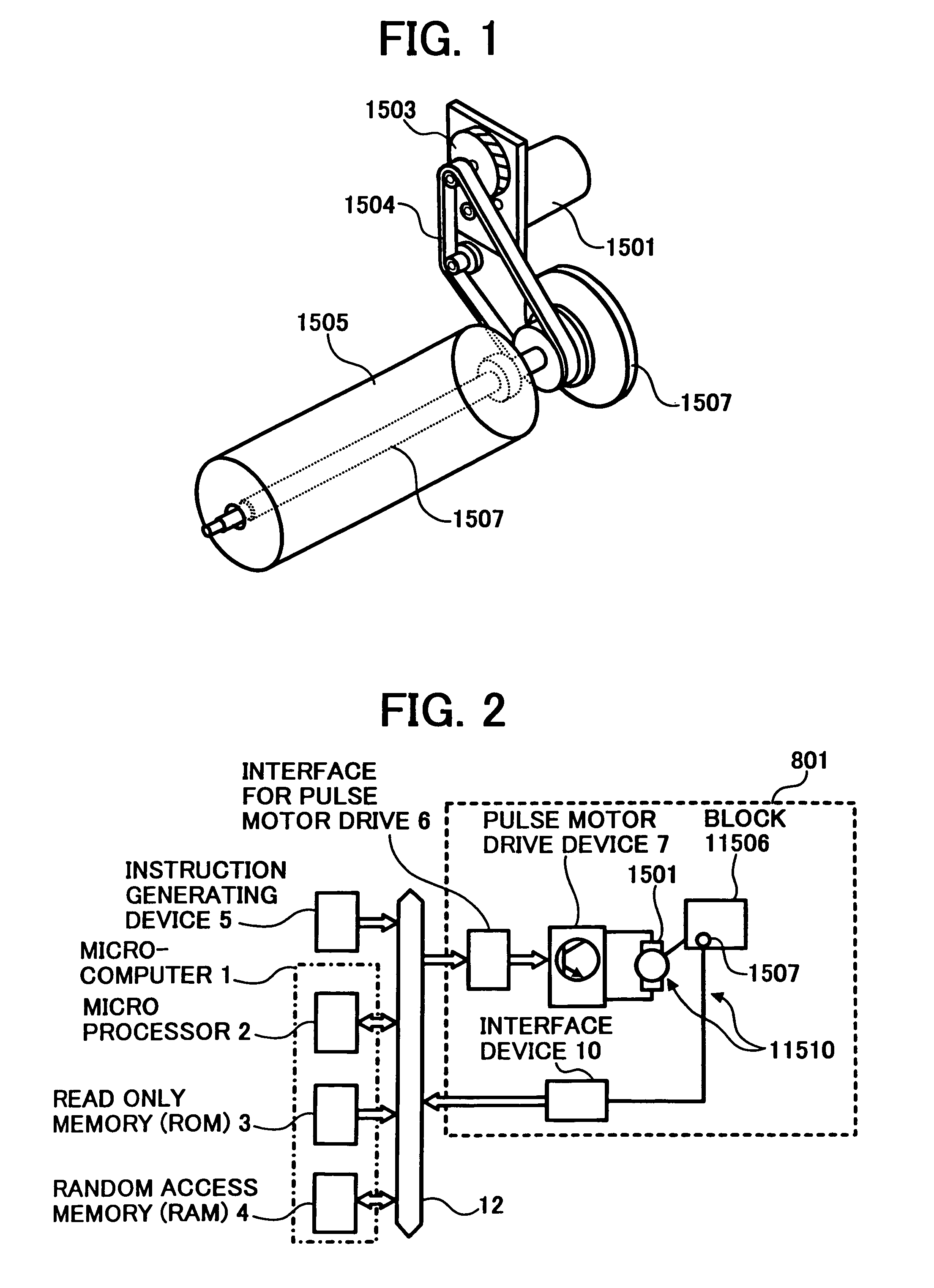
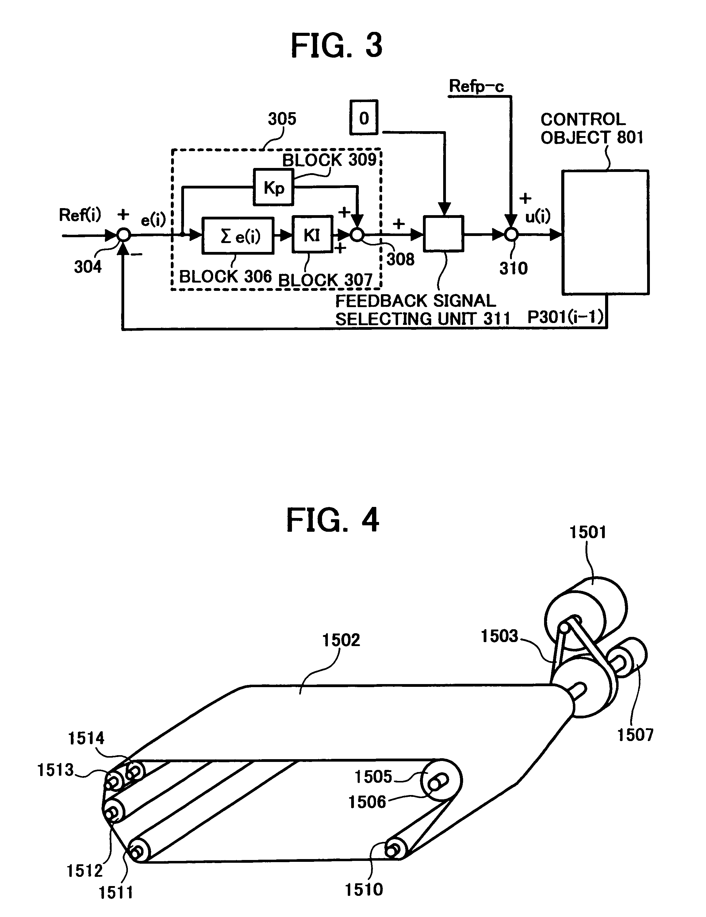
[0171] when there is abnormality, usual pulse motor drive is performed without performing feedback. Thus, a position control system in a pulse motor drive system, which is capable of carrying out accurate and highly accurate control even when there is a wrong output in a detection signal due to influence of noise or the like caused by failure and abnormality in a sensor, can be established.

[0172] Next, a second embodiment of the invention will be explained. The second embodiment is an example of a belt conveyance control method to which the invention is applied.

[0173] In FIG. 4, reference numeral 1501 denotes a pulse motor serving as a rotation drive source for driving to rotate a belt 1502. A rotation torque of the pulse motor 1501 is transmitted to the drive shaft 1506 and the drive roller 1505 for the belt by a deceleration system, for example, a timing belt 1503 constituting a power transmission system. The belt is wound around the drive roller 1505 and driven rollers 1510, 15...

second embodiment

[0183] when there is abnormality, usual pulse motor drive is performed without performing feedback. Thus, a belt position control system in a pulse motor drive system, which is capable of carrying out accurate and highly accurate control even when there is a wrong output in a detection signal due to influence of noise or the like caused by failure and abnormality in a sensor, can be established.

[0184] Next, a third embodiment of the invention will be explained. The third embodiment is an example of the belt conveyance control method.

[0185] In FIG. 7, reference numeral 1501 denotes a pulse motor serving as a rotation drive source for driving to rotate the belt 1502. A rotation torque of the pulse motor 1501 is transmitted to the drive shaft 1506 and the drive roller 1505 for the belt by a deceleration system, for example, the timing belt 1503 constituting the power transmission system. The belt is wound around the drive roller 1505 and the driven rollers 1510, 1511, 1512, 1513, and...

third embodiment

[0195] when there is abnormality, usual pulse motor drive is performed without performing feedback. Thus, a belt conveyance control apparatus in a pulse motor drive system, which is capable of carrying out accurate and highly accurate control even when there is a wrong output in a detection signal due to influence of noise or the like caused by failure and abnormality in a sensor, can be established.

[0196] Next, a fourth embodiment of the invention will be explained. The fourth embodiment is an example of the belt conveyance control method.

[0197] In FIG. 10, reference numeral 1501 denotes a pulse motor serving as a rotation drive source for driving to rotate the belt 1502. A rotation torque of the pulse motor 1501 is transmitted to the drive shaft 1506 and the drive roller 1505 for the belt by a deceleration system, for example, the timing belt 1503 constituting the power transmission system. The belt is wound around the drive roller 1505 and the driven rollers 1510, 1511, 1512, 1...


PUM


Abstract

Driving of a pulse motor is controlled in such a manner that a rotating body driven by the pulse motor rotates at a uniform angular velocity. Angular displacement of the rotating body is detected, a difference between a detection value of the angular displacement and a target value of angular displacement set in advance is calculated, and a drive pulse frequency of a drive pulse signal to be used for driving the pulse motor is calculated based on the difference and a reference drive pulse frequency. Whether the difference is added to the reference drive pulse can be selected.

Description

CROSS-REFERENCE TO RELATED APPLICATIONS [0001] The present document incorporates by reference the entire contents of Japanese priority documents, 2003-319038 filed in Japan on Sep. 10, 2003, 2003-326822 filed in Japan on Sep. 18, 2003, 2003-328598 filed in Japan on Sep. 19, 2003, 2003-376433 filed in Japan on Nov. 6, 2003, and 2004-182596 filed in Japan on Jun. 21, 2004. BACKGROUND OF THE INVENTION [0002] 1) Field of the Invention [0003] The present invention relates to a drive control method and a drive control device that use a pulse motor, a belt apparatus, an image forming apparatus, an image reading apparatus, and a computer product. [0004] 2) Description of the Related Art [0005] Conventionally, to perform position control of a rotating body, an encoder is arranged on an axis of the rotating body and the rotating body is controlled based on feedback from the encoder. The rotating body may a cylindrical drum, a circular plate, or a belt laid over at least two shafts. The positi...

Claims


Application Information

Patent Timeline
IPC IPC(8): H02P6/14
CPCH02P6/142H02P6/15
Inventor KOMATSU, MAKOTOANDOH, TOSHIYUKISAKAI, YOSHIHIRO
Owner RICOH KK
Learn More