
Capacitive measurement system

Inactive Publication Date: 2005-05-12
BAXTER LARRY K
View PDF6 Cites 169 Cited by
  • Summary
  • Abstract
  • Description
  • Claims
  • Application Information

AI Technical Summary

Benefits of technology

[0049] A fourth object is to add a guard electrode to the charge transfer circuit that eliminates or reduces the effect of stray capacitance to ground.

Problems solved by technology

A typical problem requiring measurement of small capacitance in the presence of noise is to detect the proximity of human hand, for example a hand about to be trapped in a closing automobile window or caught in a machine.
But it is very susceptible to noise.
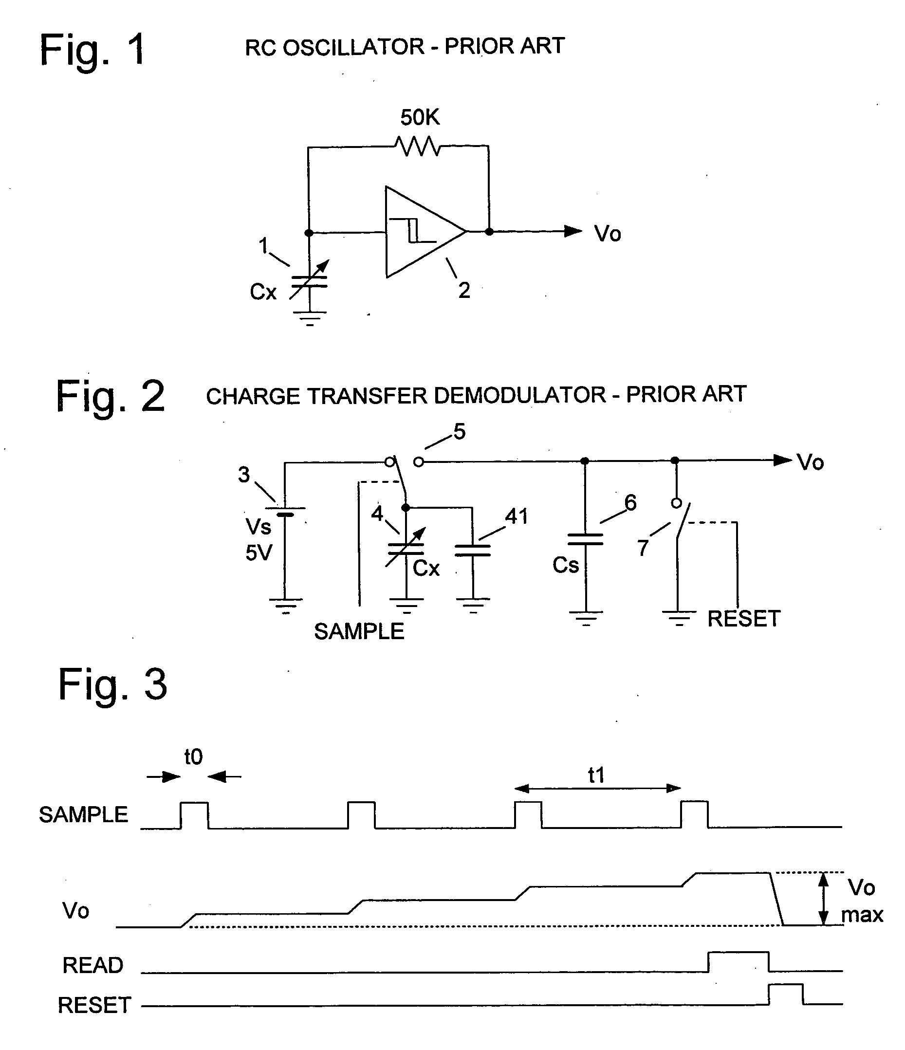
The RC oscillator of FIG. 1 is susceptible to both noise sources.
This is a serious drawback, as most industrial sites have considerable noise at power frequencies and their harmonics, peaking at 50 or 60 Hz and decreasing towards 100 kHz.
Also, impulse noise acts to increase the frequency by triggering the oscillator prematurely.
As the number of charge transfer pulses per read-reset operation increases, the noise rejection increases but the response time decreases.
However, the charge transfer circuit does not reject AC noise very well.
Another drawback of the simple circuit of FIG. 2 is that it is nonlinear, with an exponential transfer function Voi=Vs(1-ⅇ-CxCs⁢i)(2)
Also in this circuit stray capacitance 41 from the sensed node of Cx to ground adds to the measured capacitance and hurts accuracy.
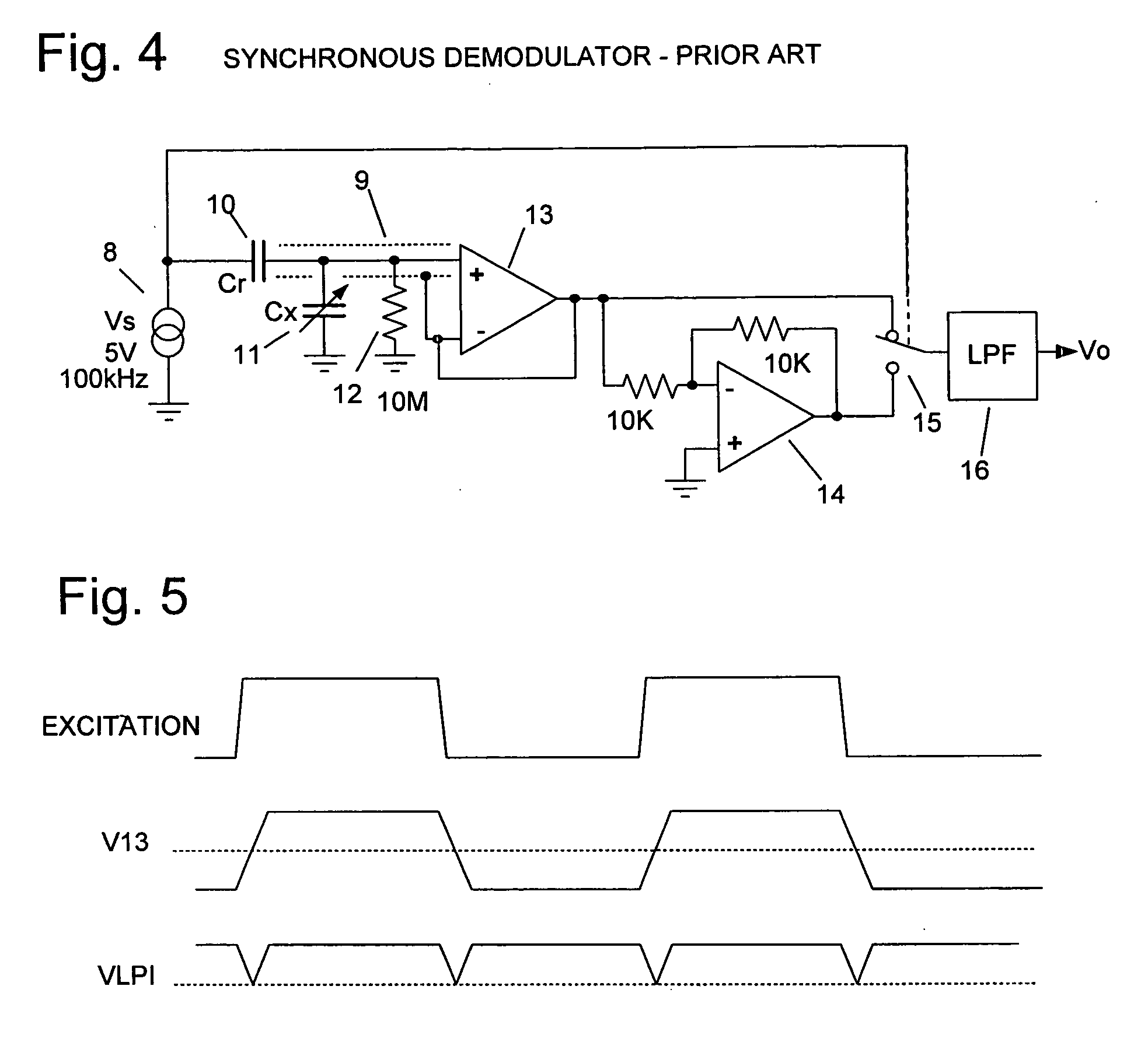
However, none of these references uses AC excitation so each is susceptible to errors due to noise.
A limitation of the synchronous demodulator circuit for low-noise applications is that this high frequency operation requires expensive, power-hungry components and may cause excessive electromagnetic radiation.

Method used


Image

  • Capacitive measurement system
  • Capacitive measurement system
  • Capacitive measurement system

Examples


Embodiment Construction

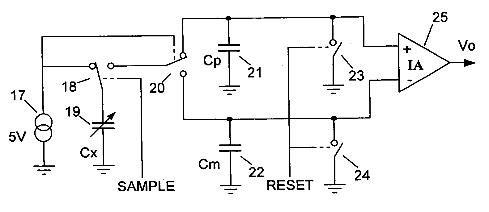
[0069]FIG. 6 and the timing diagram of FIG. 7 show a circuit with improved noise rejection, an embodiment of the current invention. First, a bipolar ± / −5V square wave 17 is connected through switch 18 to charge measured capacitor 19, Cx, to +5V. Switch 18 then is momentarily connected to switch 20 and capacitor 21 for about 20 nS during SAMPLE time to dump Cx′ charge into capacitor 21. The cycle repeats for each reversal of the excitation square wave; on negative excursions of square wave 17 switch 18 charges capacitor 19 to −5V and dumps this charge into capacitor 22.

[0070] The sample time, as shown in FIG. 7, should be delayed from the excitation so that Cx is fully charged before sampling.

[0071] Although only four cycles are shown, generally this sequence repeats at about 100 Hz for a large number of cycles, say 200, until Cp is charged to about +1V and Cm is charged to −1V. Instrumentation amplifier 25, similar to Texas Instruments' INA311, outputs VCp-VCm and the capacitors 2...


PUM


Abstract

Sensor circuits for the measurement of small variations in the value of a sensing capacitor. An alternating voltage excites the sensing capacitor a predetermined frequency whereby the voltage on the sensing capacitor reverses polarity. This voltage on the sensing capacitor is sampled each time the voltage reverses polarity. An accumulator accumulates the sampled charges from the sensing capacitor. An output signal that represents the charge in the charge accumulating means indicates the measured capacitance.

Description

CROSS REFERENCE TO RELATED APPLICATION [0001] This application is a continuation-in-part application of my co-pending application Ser. No. 10 / 188,598 filed Jul. 2, 2002 for Capacitive Measurement with Good Noise Rejection.BACKGROUND OF THE INVENTION [0002] 1. Field of the Invention [0003] This invention generally relates to capacitive measurement circuits and methods and particularly to circuits and methods for measuring small values of capacitance with good rejection of circuit and ambient noise. [0004] 2. Description of Related Art [0005] Capacitive sensors have many uses. These include measurements of pressure, humidity, motion, rotation, material composition, and proximity variables. In practice, a variable to be sensed is converted to a variable capacitance, this variable capacitance is measured, and its value is observed directly or processed by computer. The capacitance levels may range from a small fraction of a picofarad to many picofarads. [0006] A typical problem requirin...

Claims


Application Information

Patent Timeline
IPC IPC(8): G01D5/24
CPCG01D5/24
Inventor BAXTER, LARRY K.
Owner BAXTER LARRY K
Learn More