
Integrated internet camera

a technology of internet camera and camera body, applied in the field of integrated cameras, can solve the problems of large system size, lack of portability, complex and expensive prior systems, etc., and achieve the effect of being convenient and inexpensiv

Inactive Publication Date: 2005-05-12
AXIS
View PDF99 Cites 62 Cited by
  • Summary
  • Abstract
  • Description
  • Claims
  • Application Information

AI Technical Summary

Benefits of technology

[0035] Accordingly, it is an object of the invention to provide an inexpensive and efficient camera having all necessary functionality for transmission of real-time and stored digital images to the Internet in a single, portable standalone apparatus (i.e., an embedded system), without requiring the use of an external controlling apparatus such as a personal computer.
[0036] It is a further object of the invention to provide a portable, standalone camera that may initiate and independently control scheduled transmission of digital images to the Internet, where the images become available to any authorized user on the Internet.
[0039] In this manner, the portable, standalone integrated Internet camera may initiate and independently control scheduled connections to the Internet and transmission of real-time digital images to the Internet, without requiring the use of an external controlling apparatus such as a personal computer or server, and the images become available to any authorized user on the Internet. As part of a system, the portable, standalone integrated Internet camera may initiate and independently control scheduled connections to a destination shell account having a user directory at a predetermined Internet address and transmission of real-time digital images to the user directory, without requiring the use of an external controlling apparatus such as a personal computer or server, and the images become available to any authorized user on the Internet via the accessing device.
[0049] In one modification of the system, the predetermined Internet transport control protocol does not detect errors or retransmit erroneous data, thereby increasing a rate of image transfer by the file transfer device.

Problems solved by technology

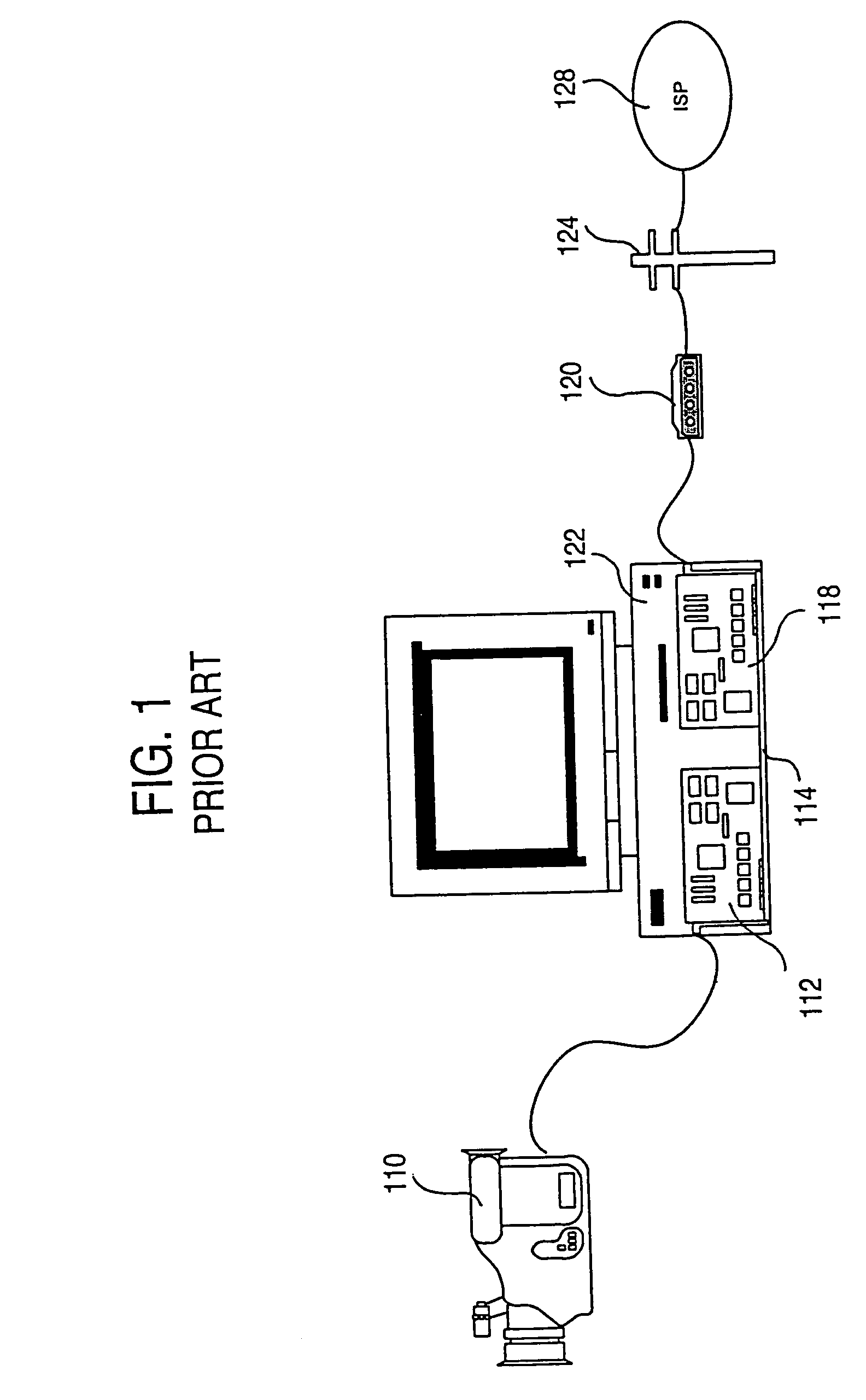
However, the prior systems are complex and expensive, requiring the use of a general purpose personal computer and a host of peripheral devices to place an image on the Internet or Web, as well as attendance by a qualified operator.
The systems are typically large and lack portability.
Moreover, such systems include many opportunities for error because of the many interfaces and communication links between discrete devices.
Such error may occur as difficulties in setup and configuration and incompatibility between devices in operation.

Method used


Image

  • Integrated internet camera
  • Integrated internet camera
  • Integrated internet camera

Examples


first embodiment

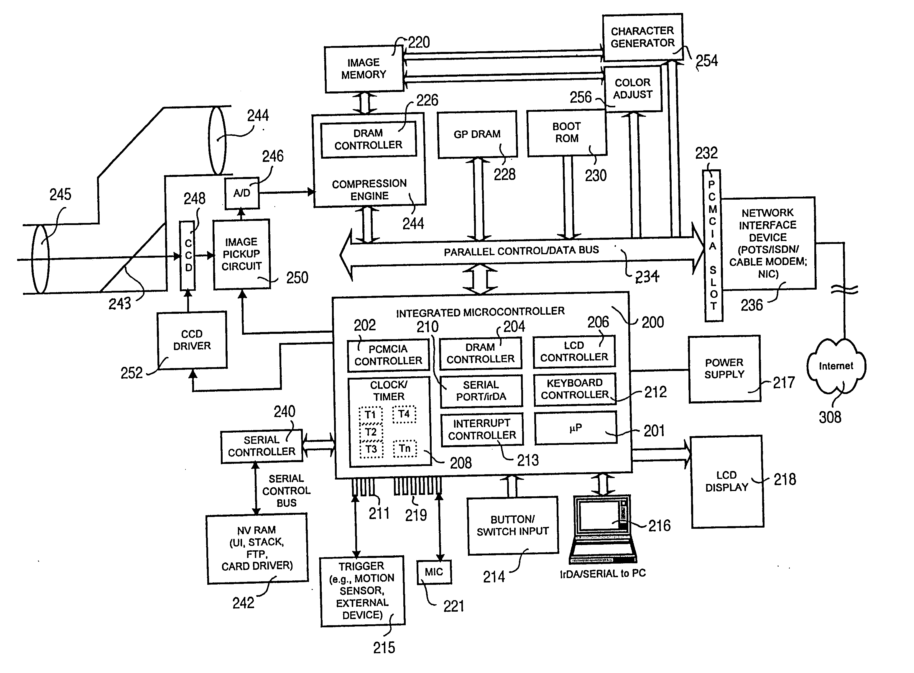
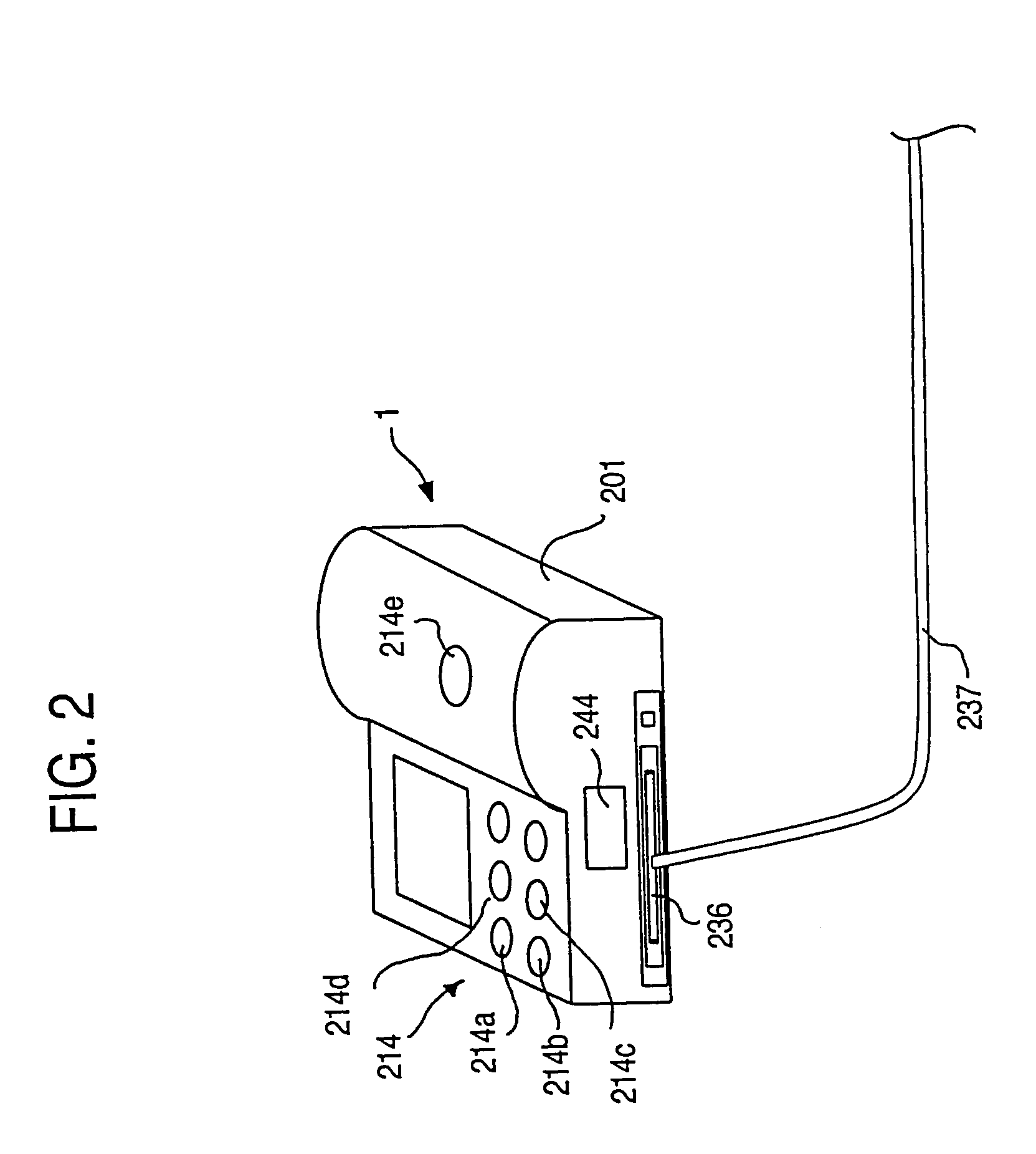
[0078]FIG. 2 shows the present invention. All of the electronic, mechanical and optical components of the integrated Internet camera 1 are housed within a camera body 201. Accordingly, in the context of this specification, “integrated” is equivalent to “self-contained” , such that all the noted components are supported on or situated within the body or casing. As shown in FIG. 2, the camera 1 may be connected to the Internet via a network interface device 236 (comprising, e.g., a modem or network card) and a connection cable 237 (which may be a telephone wire connected to the public network or a network cable connected to a local or wide area network). Preferably, the camera body includes a threaded camera mount, and is sized and shaped to fit industry standard environmental housings for outdoor use.

[0079] A viewfinder 244 allows the operator to view a scene corresponding to, or identical to, an image formed on an image pickup (shown in FIG. 3) of the camera 1 via an image-forming o...

second embodiment

[0115] The REPORTING menu / storage area allows the setting of error and status reporting parameters. An ADDRESS variable group stores a destination (E-mail) address to which error, attachments (image files) and status reports (with or without attachments) are sent, and a flag that sets the level of detail of the reports. A REPORTS variable group defines what is reported, including whether errors are reported, whether each (e.g., interval or timed) upload is reported, whether changes in the parameters or settings are reported, whether an image file attachment will be sent as a report and which slot(s) will be sent (including the possibility of an entire batch list), and the number of retries and interval therebetween should the camera 1 fail to report. An ERROR REPORTING variable group defines which types of errors are reported, including errors such as login failure, data rate too slow, general I / O error, FTP error, modem failure, reset, and pan / tilt error (if applicable—primarily fo...

third embodiment

[0185] The image converter 222 is connected to a conventional camcorder or CCTV 110 that supplies an NTSC or PAL signal of the scene at which the camcorder 110 is directed. It should be noted that the connection is not necessarily to a camcorder or CCTV, but may be to any NTSC or PAL source, e.g., a VTR, television tuner, etc. Accordingly, the invention avoids the use of a complicated setup requiring a stand-alone personal computer.

[0186] Otherwise, the third embodiment of the invention operates substantially identically to the manner in which the first embodiment operates, including the description relating to FIGS. 4-16.

[0187]FIG. 21 shows a block diagram of an Internet camera according to a fourth embodiment of the present invention. As shown in FIG. 21, the fourth embodiment of the invention utilizes the same fundamental operating core as the first embodiment. Accordingly, a description of elements already described with reference to the first embodiment and to FIGS. 2-16 (i.e....


PUM


Abstract

An integrated Internet camera includes, as embedded components contained within the camera body and controlled by a microcontroller, at least a network interface device for connecting to the Internet, a transport control device for packetizing according to Internet protocols, a file transfer device for communicating with a destination user directory on the Internet, and a transmission initiating device for initiating the connection and transfer operations of the file transfer device and transport control device. The network interface device may be a modem, network adapter, or adapter for connection to the Internet. Upon capturing the digital image, the camera initiates a connection to the Internet, connects to the destination user directory, and uploads the digital images. Thereafter, the digital images are available to authorized (or any) user having access to the Internet.

Description

[0001] The present application is a division of U.S. patent application Ser. No. 10 / 865,904, filed Jun. 14, 2004, which is a division of U.S. patent application Ser. No. 09 / 204,289, filed Dec. 3, 1998, and claims the benefit of U.S. Provisional Application 60 / 085,585, filed May 15, 1998, and U.S. Provisional Application 60 / 067,310, filed Dec. 4, 1997, all of which are expressly incorporated herein by reference in their entireties.BACKGROUND OF THE INVENTION [0002] 1. Field of the Invention [0003] The present invention relates to an integrated camera for connecting to the Internet and transmitting images over the Internet. [0004] 2. Description of Background Information [0005] As the Internet (i.e., the worldwide inter-network, currently operated under TCP / IP: Transmission Control Protocol / Internet Protocol) gains more participants and becomes more consumer-oriented, the demand for simplified ways of providing access to various media increases. A large portion of the new participants...

Claims


Application Information

Patent Timeline
Patent Type & Authority Applications(United States)
IPC IPC(8): H04N1/00G06F13/00H04N5/222H04N5/225H04N5/232H04N7/16H04N7/18H04N11/00
CPCH04N1/00214H04N1/00217H04N1/00244H04N2201/0084H04N5/232H04N5/23203H04N5/23206H04N1/00854H04N1/00838H04N23/66H04N23/661H04N23/695H04N19/164H04N19/172
Inventor CREAMER, ROBKNAPP, WALTERKOCH, MARKARAKI, YOSHIYUKIHELTON, RICHARD
Owner AXIS
Learn More