Stacked phase shift sheet, stacked polarizing plate including the same and image display

a phase shift sheet and polarizing plate technology, applied in the field of laminated retardation plates, can solve the problems of reducing display quality, thick, providing a narrow retardation value range, and increasing film thickness, so as to reduce thickness, prevent coloring, and excellent optical properties

Inactive Publication Date: 2005-05-12
NITTO DENKO CORP
View PDF13 Cites 40 Cited by
  • Summary
  • Abstract
  • Description
  • Claims
  • Application Information

AI Technical Summary

Benefits of technology

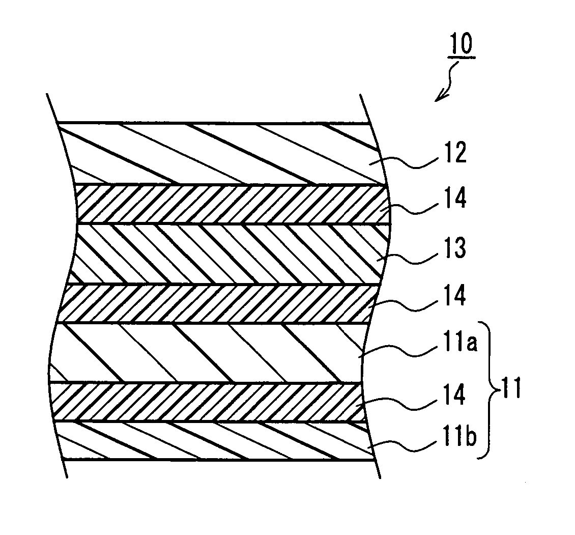
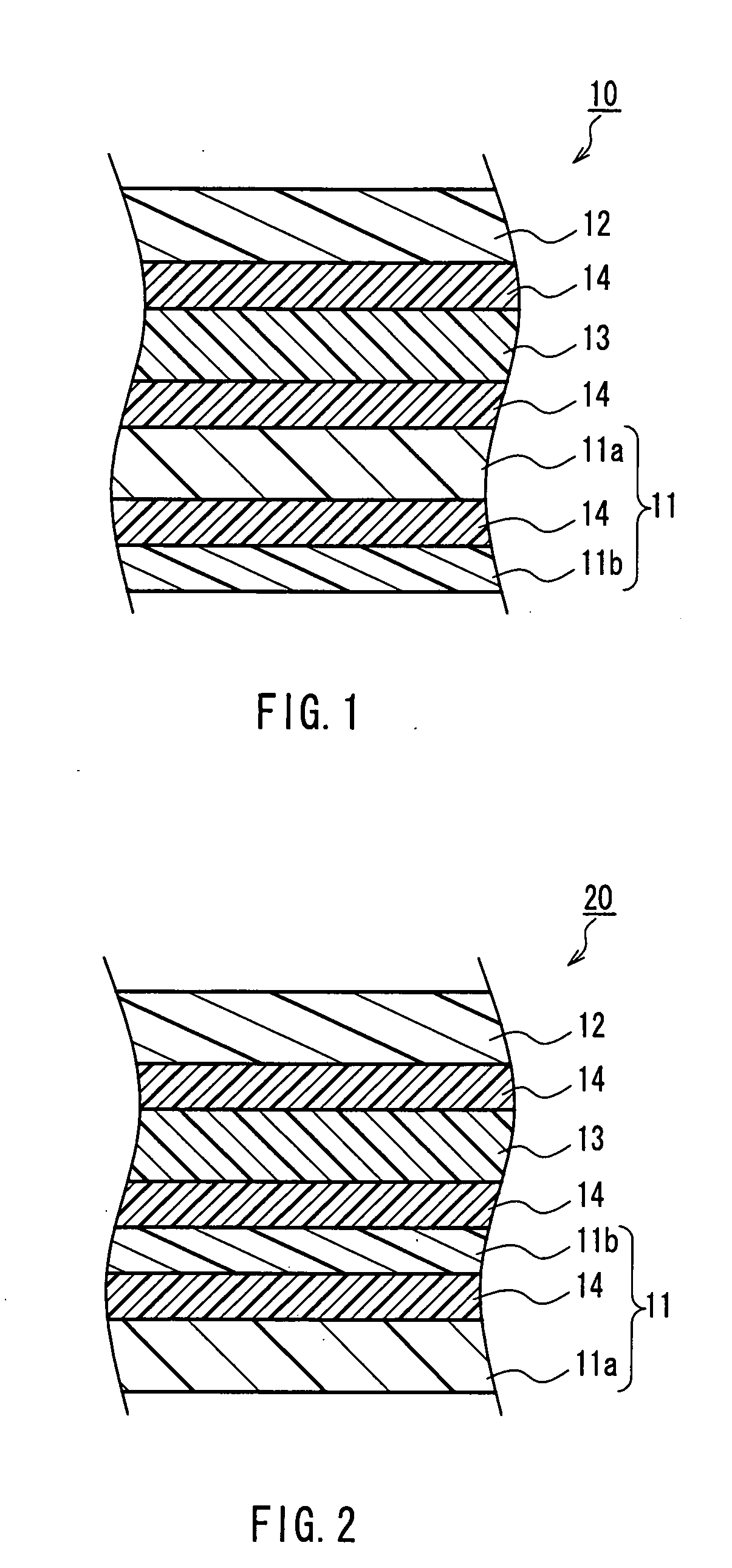
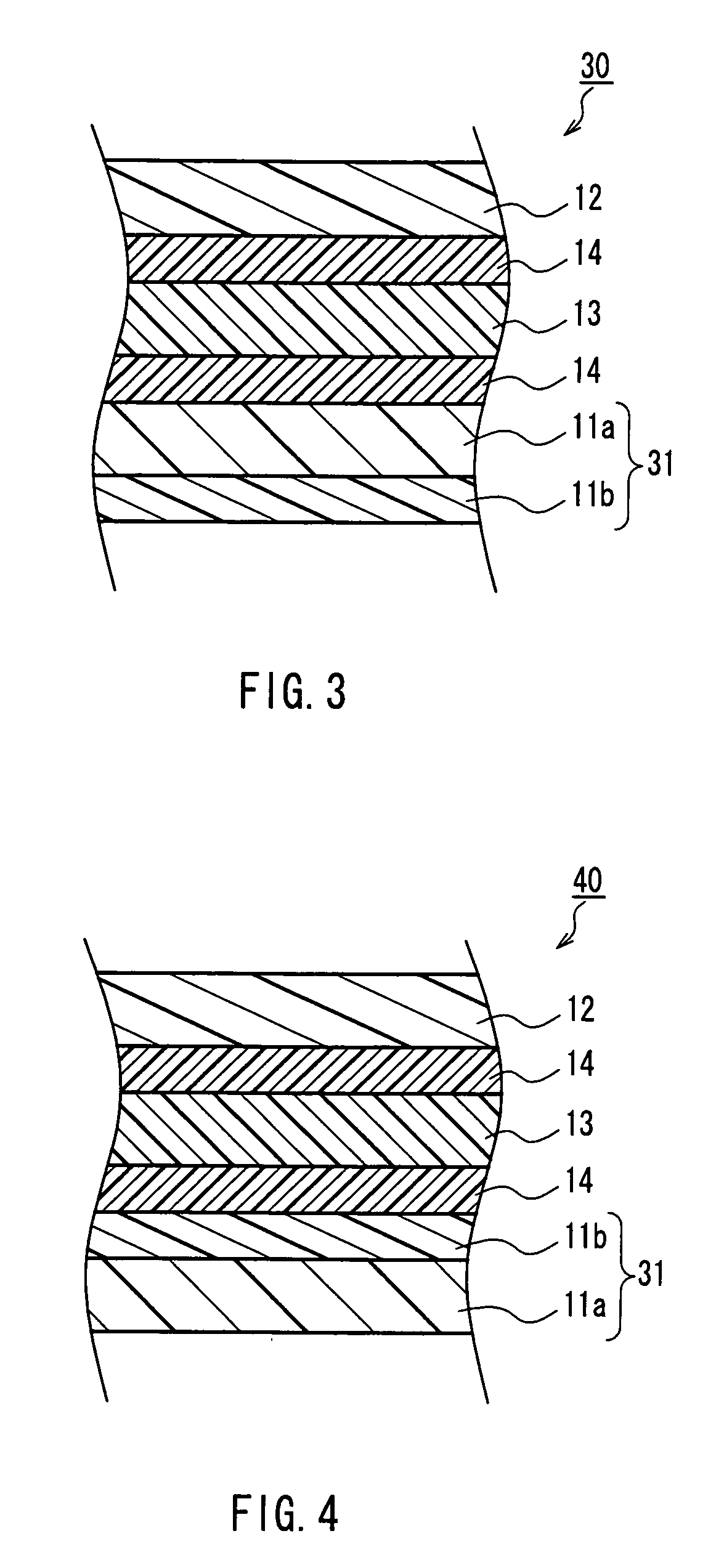
[0008] The inventors have found a laminated retardation plate that shows excellent optical properties, such as the in-plane retardation (Re) of 10 nm or more and the difference (Rth−Re) of 50 nm or more, and has a reduced thickness, by laminating the optically anisotropic layer (A) made of a polymer and the optically anisotropic layer (B) made of a non-liquid crystalline polymer such as polyimide. Furthermore, in such a laminated retardation plate, it is possible to prevent coloring that may occur as

Problems solved by technology

Although the laminated retardation plate had an advantage of a wide range of retardation values that is obtained by a combination of the stretched films, it also had a disadvantage that lamination of thick films would further increase the film thickness.
On the other hand, though the monolayer retardation plate that includes a single layer is advant

Method used


Image

  • Stacked phase shift sheet, stacked polarizing plate including the same and image display
  • Stacked phase shift sheet, stacked polarizing plate including the same and image display
  • Stacked phase shift sheet, stacked polarizing plate including the same and image display

Examples


examples

[0163] The following is a further description of the present invention, with reference to Examples and Comparative examples. It should be noted that the present invention is not limited to these Examples alone. The optical properties and the thickness were measured in the following manner.

(Measurement of Retardation Value)

[0164] The retardation value was measured using a retardation meter applying a parallel Nicol rotation method as a principle (manufactured by Oji Scientific Instruments, trade name: KOBRA21-ADH) (measurement wavelength: 610 nm).

(Film Thickness Measurement)

[0165] The thickness was measured with DIGITAL MICROMETER-K-351C (trade name) manufactured by Anritsu.

example a-1

[0166] A norbornene film having a thickness of 100 μm was subjected to a tenter transverse stretching at 175° C. The stretch ratio was 1.4 its pre-stretch length in the stretching direction. Thereby, an optically anisotropic layer (A) having a thickness of 69 μm, Re(A)=67 nm, and Rth(A)=136 nm, was obtained. Polyimide (weight average molecular weight: 59,000), which was synthesized from 2,2′-bis(3,4-dicarboxydiphenyl)hexafluoropropane) and 2,2′-bis(trifluromethyl)-4,4′-diamino biphenyl was dissolved in cyclohexanone, thereby a 15 wt % polyimide solution was prepared. After coating this polyimide solution on a biaxially stretched PET film, the coating film was dried (temperature: 150° C.; time: 5 minutes), thereby an optically anisotropic layer (B) having a thickness of 3 μm was formed on this stretched PET film. This optically anisotropic layer (B) had optical properties of Re(B)=3 nm, Rth(B)=110 nm, and Rth(B) / Re(B)=32.7. Then, after adhering the optically anisotropic layer (B) on ...

example a-2

[0167] A polyester film having a thickness of 70 μm was subjected to a longitudinal stretching at 160° C. The stretch ratio was 1.1 its pre-stretch length in the stretching direction. The thus obtained optically anisotropic layer (A) was 64 μm in thickness, Re(A)=65 nm, Rth(A)=70 nm, and Rth(A) / Re(A)=1.1. Next, on this optically anisotropic layer (A), a polyimide solution prepared as in Example A-1 was coated directly, and the coating film was dried (temperature: 150° C.; time: 5 minutes) so as to form an optically anisotropic layer (B) on the optically anisotropic layer (A), thereby producing a laminated retardation plate. The optically anisotropic layer (B) was 5 μm in thickness, and the optical properties were: Re(B)=5 nm, Rth(B)=180 nm, and Rth(B) / Re(B)=36.0. The optical properties of the optically anisotropic layer (B) were measured after peeling from the optically anisotropic layer (A).


PUM


Abstract

The present invention provides a laminated retardation plate that shows an excellent viewing angle property when used in a liquid crystal display, and that can be decreased in thickness. The laminated retardation plate is formed by laminating an optically anisotropic layer (A) made of a polymer having an in-plane retardation of 20-300 nm and a ratio between a thickness direction retardation and the in-plane retardation of not less than 1.0, and an optically anisotropic layer (B) made of a non-liquid crystalline polymer such as polyimide having an in-plane retardation of not less than 3 nm and a ratio between a thickness direction retardation and the in-plane retardation of not less than 1.0. The thus obtained laminated retardation plate shows excellent optical properties, e.g., an in-plane retardation (Re) of 10 nm or more, and a difference between a thickness direction retardation and the in-plane retardation of 50 nm or more.

Description

TECHNICAL FIELD [0001] The present invention relates to a laminated retardation plate, a laminated polarizing plate using the same, and various image displays using the same. BACKGROUND ART [0002] Conventionally, various image displays require retardation plates with controlled refractive indices in order to realize excellent display grades in all orientations, and the types are selected depending on the display methods or the like of the liquid crystal displays. It should be noted particularly that a VA (vertically aligned) type or an OCB (optically compensated bend) type liquid crystal display requires a retardation plate providing refraction indices (nx, ny, nz) in three axial directions (X-axis, Y-axis and Z-axis) being ‘nx>ny>nz’, i.e., showing an optically negative biaxiality. Known examples of the retardation plate satisfying ‘nx>ny>nz’ include a laminated retardation plate formed by laminating two stretched polymer films subjected to a free-end uniaxial stretchin...

Claims


Application Information

Patent Timeline
IPC IPC(8): G02B5/30G02F1/13363
CPCG02F1/133634G02B5/3016G02F1/1335G02F1/13363G02B5/30
Inventor NISHIKOUJI, YUUICHISASAKI, SHINICHIYAMAOKA, TAKASHIMURAKAMI, NAOYOSHIMI, HIROYUKIHAYASHI, MASAKI
Owner NITTO DENKO CORP
Why Eureka
Try Eureka