Raman amplifier and optical relay transmission system

Active Publication Date: 2005-05-12
MITSUBISHI ELECTRIC CORP
View PDF15 Cites 20 Cited by
  • Summary
  • Abstract
  • Description
  • Claims
  • Application Information

AI Technical Summary

Benefits of technology

[0011] It is an object of the present invention to solv

Problems solved by technology

One of the main problems in optical relay systems using an optical amplification of a wavelength-multiplexed signal light is the wavelength-dependent gain characteristics in an optical amplifier.
However, one of the disadvantages of the Raman amplifier is that the wavelength characteristic of the gain also changes when the average gain of the Raman amplifier changes. FIG. 5 is a graph illustrating an example of the wavelength characteristic of a Raman gain, which is obtained by Raman-amplifying a signal light in the wavelength range of 1570 nm to 1608 nm with a backward excitation lights of 1470 nm and 1500 nm using a single mode fiber (SMF).
Because of this, even though the power of the excitation light of plural wavelengths is optimally distributed in the Raman amplifier, it is not possible to change only the average gain without changing the wavelength-dependent gain profile.
Thi

Method used


Image

  • Raman amplifier and optical relay transmission system
  • Raman amplifier and optical relay transmission system
  • Raman amplifier and optical relay transmission system

Examples


first embodiment

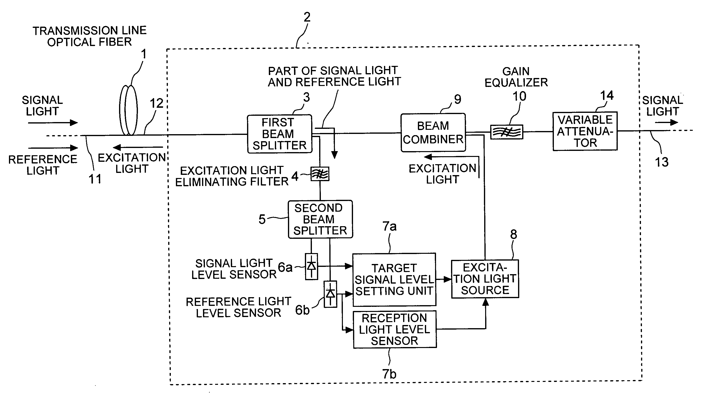
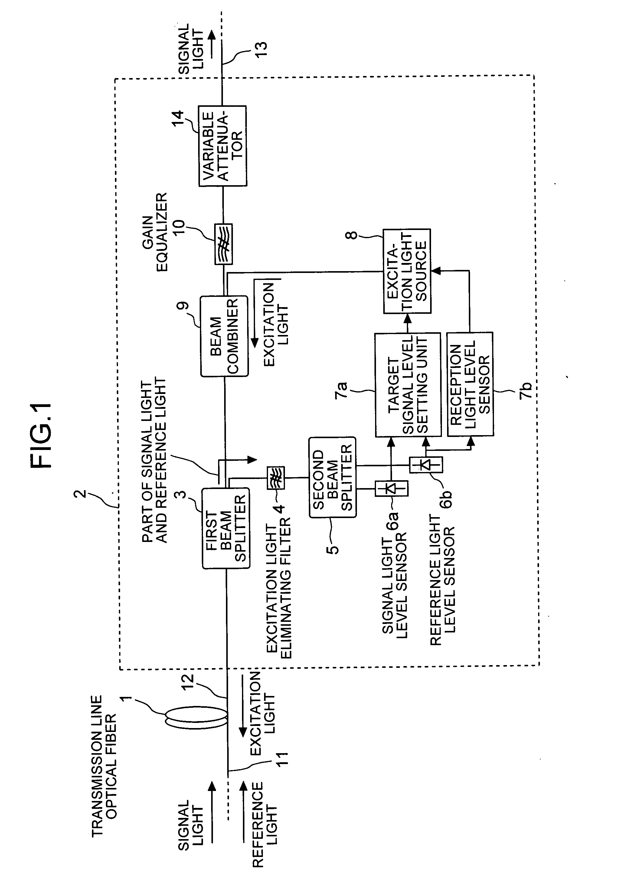
[0021]FIG. 1 is a block diagram of a Raman amplifier according to the present invention. The Raman amplifier 2 is a transmission line through which a signal light that is multiplexed with a signal light of 1580 nm wavelength and a reference light of 1510 nm wavelength is propagated. A transmission line optical fiber 1, which achieves the Raman amplification effect when an excitation light is input, is connected to the input end of the Raman amplifier 2. An optical fiber 13, which outputs the Raman-amplified signal light, is connected to the output end of the Raman amplifier 2.

[0022] The Raman amplifier 2 includes an excitation light source 8 that emits the excitation light of a wavelength required for the Raman amplification of the signal light of 1580 nm wavelength propagated through the transmission line optical fiber 1, and a beam combiner 9 that combines plural excitation lights from the excitation light source 8. The excitation light source 8 includes a laser oscillator such as...

second embodiment

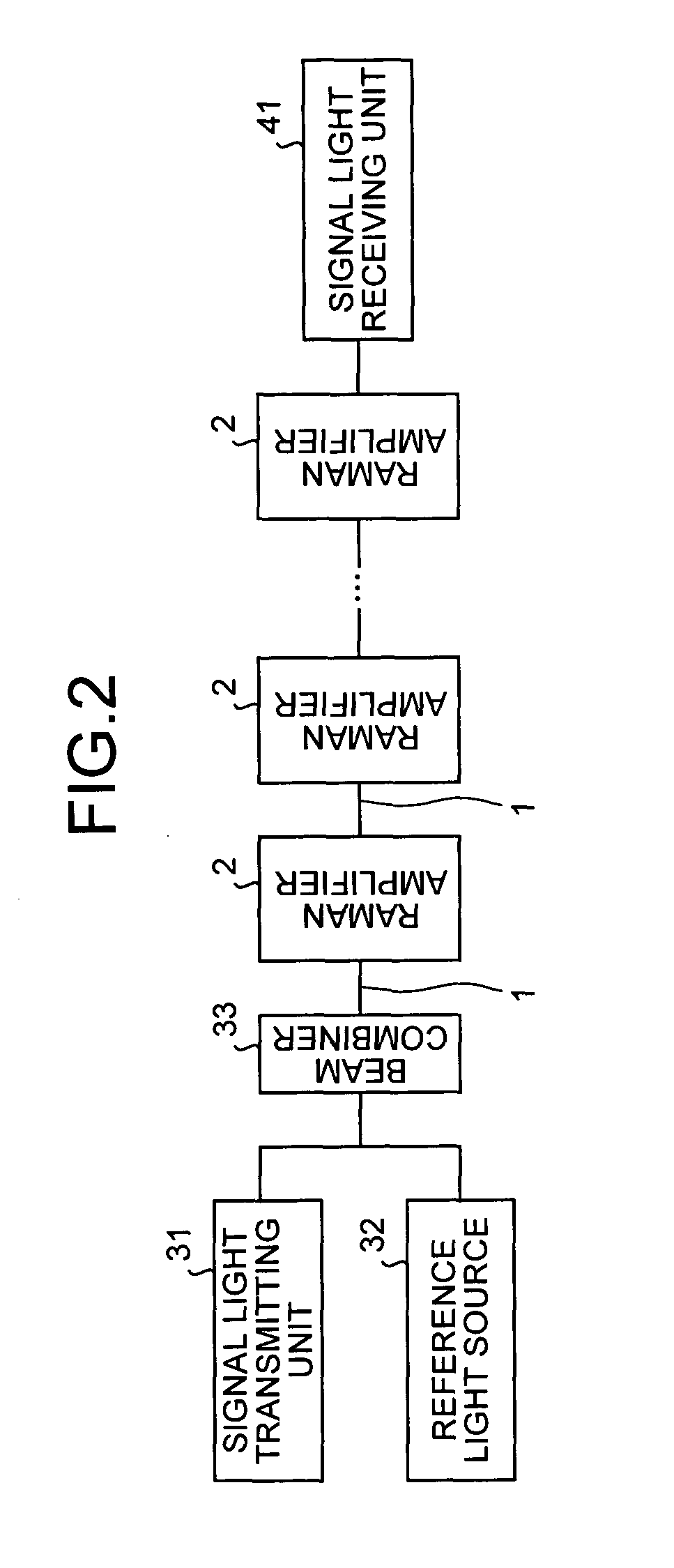
[0048] in addition to the amplifier in the constant gain EDFA 15 that is conventionally employed as the optical relay transmission system, the optical relay transmission system further includes the Raman amplifier. Consequently, even when the gain efficiency of the transmission line optical fiber 1 varies or when the loss of the excitation light along the connection path of the transmission line optical fiber 1 varies, the desired Raman gain can be achieved by appropriately adjusting the output power of the excitation light source 8. Along with enhancing the transmission distance of the amplified signal light, the signal light can be further amplified while suppressing the loss and maintaining the gain at a constant level.

[0049] According to the first and second embodiments, the excitation light from the excitation light source 8 is propagated in the direction opposite to that of the signal light. However even when the excitation light is propagated in the same direction as that of...


PUM


Abstract

An optical fiber propagates and amplifies a second signal light that is a wavelength-multiplexed signal of a first signal light of a plurality of wavelengths and a reference light that is out of a wavelength range of amplification. An excitation light source outputs an excitation light for amplifying the second signal light. A beam splitter splits a portion of the second signal light into the first signal light and the reference light. A signal light level detecting unit detects a level of the first signal light. A reference light level detecting unit detects a level of the reference light. A signal level setting unit calculates a target value for constantly maintaining a Raman gain, and controls the output level of the excitation light in such a way that the first signal level matches with the target value.

Description

BACKGROUND OF THE INVENTION [0001] 1) Field of the Invention [0002] The present invention relates to a technology to improve gain and wavelength characteristics of a Raman amplifier for a reliable optical transmission system. [0003] 2) Description of the Related Art [0004] One of the main problems in optical relay systems using an optical amplification of a wavelength-multiplexed signal light is the wavelength-dependent gain characteristics in an optical amplifier. To achieve quality transmission characteristics of a signal light, it is required to limit the level of each signal component of a different wavelength within a desired range to suppress signal degradation, such as a degradation of the S / N ratio due to a nonlinear effect of the transmission line and / or amplified spontaneous emission. This necessitates a proper design of the wavelength characteristics of the gain in the optical amplifier, such that the variation in the signal light level of each wavelength component can be...

Claims


Application Information

Patent Timeline
IPC IPC(8): H01S3/10G02F1/35H01S3/30H04B10/077H04B10/079H04B10/29H04B10/294H04J14/00H04J14/02
CPCH04B10/2916
Inventor TOKURA, TOSHIYUKIKOGURE, TAICHIKAJIYA, SATOSHIMIZUOCHI, TAKASHI
Owner MITSUBISHI ELECTRIC CORP
Why Eureka
Try Eureka