Flange assembly of an optical system

a technology of optical systems and flanges, applied in the direction of instruments, photomechanical equipment, optical elements, etc., can solve the problems of impermissible deformation of precision systems, irreversible changes in frictional connections or components, and maladjustment of projection objectives, so as to achieve restricted rigidity, clean and more precise surfaces, and reduce the effect of rigidity

a technology of optical systems and flanges, applied in the direction of instruments, photomechanical equipment, optical elements, etc., can solve the problems of impermissible deformation of precision systems, irreversible changes in frictional connections or components, and maladjustment of projection objectives, so as to achieve restricted rigidity, clean and more precise surfaces, and reduce the effect of rigidity

US20050099704A1Active Publication Date: 2005-05-12CARL ZEISS SMT GMBH

Image

  • Flange assembly of an optical system
  • Flange assembly of an optical system
  • Flange assembly of an optical system

Examples


Embodiment Construction

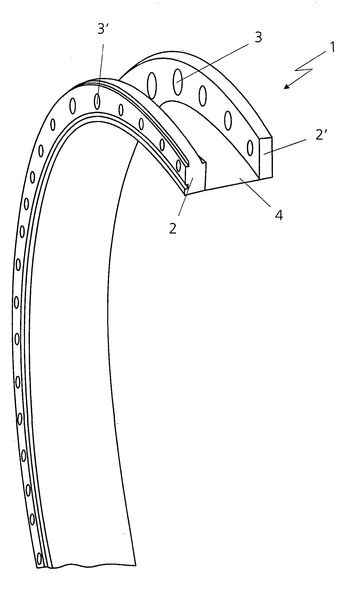
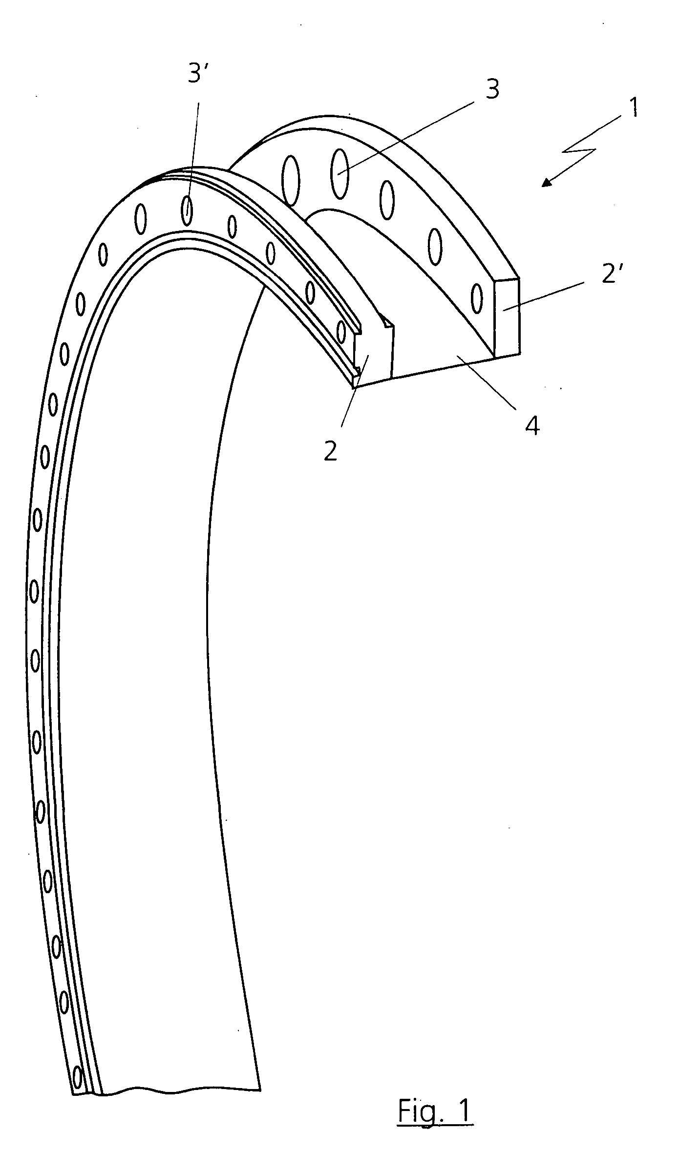
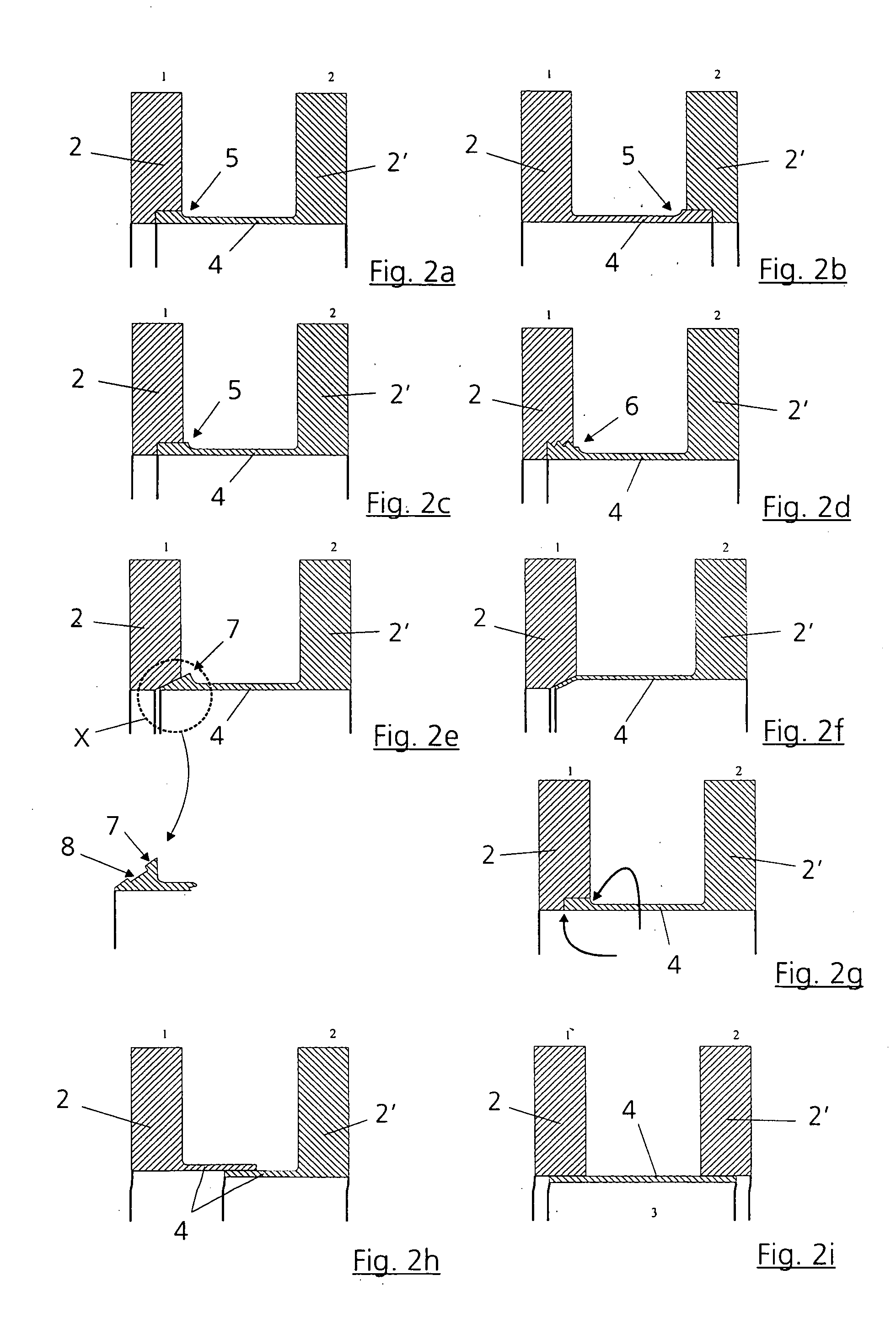
[0020]FIG. 1 shows a device or flange assembly 1 which has two flanges 2 and 2′ which are preferably embodied as annular flanges. The flanges 2 and 2′ serve the purpose of connecting two components such as, for example, a lens with a lens mount as optical assembly, and a support structure, for example an objective housing, as illustrated in principle in FIG. 3. The two flanges 2, 2′ each have mutually differing coefficients α1 and α2 of linear thermal expansion, the flanges 2 and 2′ being able in each case to have one coefficient of thermal expansion which can correspond approximately to that of the respectively adjacent component. The flanges 2 and 2′ are provided with bore holes 3 and 3′, the components, in particular the lens mount and the support structure, being able to be connected to the flanges 2 and 2′ via screwed connections. The flanges 2 and 2′ are connected to one another via a compensation element or connecting element 4. The compensation element 4 preferably has a thi...


PUM

PropertyMeasurementUnit
thicknessaaaaaaaaaa
thicknessaaaaaaaaaa
coefficients of linear thermal expansionaaaaaaaaaa

Abstract

A flange assembly (1) of an optical system has a first flange (2), a compensation element (4) and a second flange (2′). The flanges (2, 2′) and the compensation element (4) are substantially axially symmetric both flanges (2, 2′) being suitable for being connected to other components (10, 11) of the optical system in a non-destructive, non-positive axially separable fashion. The two flanges (2, 2′) consist of different materials with different coefficients of linear thermal expansion. The compensation element (4) is radially soft, but connects the two flanges (2, 2′) rigidly in their relative spatial position.

Description

BACKGROUND OF THE INVENTION PRIORITY CLAIM [0001] Priority under 35 U.S.C. §119 is hereby claimed to German Patent Application Serial No. 103 52 820.2 filed Nov. 12, 2003. [0002] 1. Field of the Invention [0003] The invention relates to a flange assembly of an optical system. The invention relates, furthermore, to a method for connecting two flanges. The invention likewise relates to an objective, in particular a projection objective in semiconductor lithography. [0004] 2. Description of the Related Art [0005] When connecting two components with different coefficients of thermal expansion, the temperature-induced changes in diameter of the components result in stresses which can lead in precision systems to impermissible deformations, irreversible changes in frictional connections or destruction of components. [0006] Particularly in the case of projection exposure machines with projection objectives for producing semiconductors, even minimal changes can lead to maladjustment of the ...

Claims


Application Information

Patent Timeline
12 May 2005
Publication
US20050099704A1
IPC
G02B7/00; G02B7/02; G03F7/20; H01L21/027
CPC
G02B7/008; G02B7/028; G03F7/7095; G03F7/70833; G03F7/70891; G03F7/70825
Inventors
RAU, JOHANNES; MAHLMANN, MARTIN