Method for forming multilayer release liners and liners formed thereby

a technology of release liners and release liners, which is applied in the field of multi-layer release liners and their methods, can solve the problems of stringent restrictions on solvent recovery, increase the cost of end product adhesive construction, so as to improve the optimization of the coating process

Inactive Publication Date: 2005-05-12
AVERY DENNISON CORP
View PDF78 Cites 12 Cited by
  • Summary
  • Abstract
  • Description
  • Claims
  • Application Information

AI Technical Summary

Benefits of technology

[0008] The present invention advantageously provides an efficient method of creating multilayer release liners, thereby overcoming the problems resulting from the prior art processes. The present invention achieves these benefits by providing a method of coating both a support layer and a release layer on a substrate substantially simultaneously. Consequently, separate coating steps are eliminated, and a corresponding savings in both time and costs are achieved.
[0009] Generally, these advantageous results may be achieved by at least two different coating methods. The first method achieves these results by modifying the die used to coat the support layer and a release layer (e.g., silicone layer) so that the die can dispense the fluids of both layers substantially simultaneously at a single coating station. The die dispenses the support layer onto the substrate, and substantially simultaneously, the release layer on the support layer. There is no need for a separate drying, hardening or curing step to prevent the layers from intermixing. By controlling the coating gap between the die and substrate, the processing conditions of the modified die may be optimized to achieve the most stable and efficient deposition of these layers. In some embodiments, application of controlled vacuum to the dual die coating process may be used to improve coating efficiency, increase coating tolerances and provide for less penetration of coated fluids onto the substrate to be coated. The multilayer release surfaces resulting from the simultaneous dual die coating of support layer and silicone-containing layer are also believed to have a unique morphology and advantageous properties.
[0010] Simultaneous coating of the support and release layers to form a multilayer release surface may also be achieved by curtain coating. For example, a slide coat die may be modified to have two slots, with the upper slot metering the release layer and the lower slot the support layer. The release layer and support layer combine on the die face surface, and fall to the moving substrate as a multilayer liquid sheet. The distance between the die and the substrate may range from 5 cm to 50 cm, and more preferably, from 10 cm to 30 cm. Advantageously, curtain coating techniques do not require as precise an optimization of the coating gap between the die and the substrate to generate high speed coatings, and high coating speeds are easily obtained.

Problems solved by technology

However, use of these high quality papers increases the cost of the end product adhesive construction, because such papers are typically much more expensive than regular open papers.
Growing concern over the environment has imposed stringent restrictions regarding recovery of the solvent used in applying the solvent based silicone to the high-holdout backing paper or other materials.
When applied to porous low cost papers, such as machine finished (MF) or machine glazed (MG) papers, these materials soak into the paper (penetrate the paper surface) to give ineffective coverage of the paper fibers unless excessively high quantities of expensive silicone are used.
Ineffective coverage of the paper fibers provides unsuitable release liners for PSA applications, especially where high speed convertibility is an essential performance feature.
However, there are several drawbacks to this prior art process.
First, additional costs are incurred because the prior art methods require two coating steps.
Otherwise, there is a potential for undesirable intermixing or destruction of the respective layers.
Second, because two separate coating steps are required, more time is needed for the overall formation of the release liner.

Method used


Image

  • Method for forming multilayer release liners and liners formed thereby
  • Method for forming multilayer release liners and liners formed thereby
  • Method for forming multilayer release liners and liners formed thereby

Examples


examples

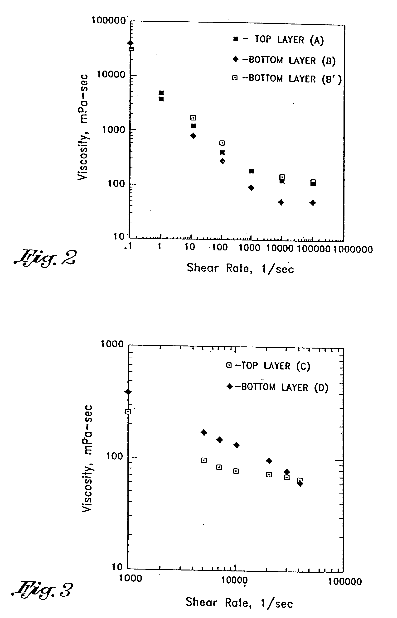
[0068] The release properties of the liners of Examples 1-22 were quantified using two methods, the 90° peel release force and the 180° peel release profile. The 90° peel release force was measured on a TLMI Lab Master instrument in the liner off mode, at a rate of 7.62 m / min, and results were measured in cN / 25 mm. The 180° release profile was generated by measuring the peel release force on an Instrumentors ZPE-1000 High Rate Peel Tester at rates of 10, 30, 100, 200, and 300 m / min. in the liner off mode, and results were measured in cN / 25 mm. Protocols for performing the tests are as follows:

90% Peel Release Force

[0069] This test method allows the end user to determine the force required to separate the release backing form the pressure sensitive adhesive coated face material. The release force is defined as the force required to separate a pressure sensitive adhesive coated material from its release surface (or vice versa) at an angle of 90° and a jaw separation rate of 7.62 m p...

examples 1 and 2

[0077] Examples 1 and 2 compare the relative release properties of release surface formed from a coating having 100% silicone solids to a release surface formed from a coating having 40% silicone solids. In each case, the silicone containing layer was coated on a release Support layer (RSL), where the RSL comprised a filler material coated on paper.

[0078] Example 1 consists of a General Electric silicone release layer coated on synthetic SBR as a RSL support layer, which in turn was coated on AT-70 paper. The top layer was prepared by mixing GE 1111-11-259 (62.7g), GE 1192-05-117 (3.3 g), and water (34.0 g). Because no solids other than silicone were coated to form the release layer, the release layer of Example 1 is formed from 100% silicone solids. The bottom RSL layer is 33% solid synthetic SBR filler. The coating was applied to AT-70 paper using a dual die at coating speed of 200 m / min, and cured at 160° C. for 4 seconds to produce the finished liner. The coat weight is 1.5 g / m...

examples 3-6

[0081] Examples 3-6 consist of Wacker silicone as a release layer coated on Air Products Airflex 465 as a RSL, which was coated on either Data-70 or Willamette paper. The top layer was prepared by mixing Wacker 38197 VP (66.0 g). Wacker crosslinker V20 (3.5 g), 10% solution of 3M Fluorad fluorochemical surfactant FC-129 (0.7 g), 1% aqueous Cellosize Hydroxyethyl Cellulose QP-100 MH (7.5 g), and water (22.3 g). The bottom RSL layer was prepared by mixing Air Products Airflex 465 (52.3 g) and water (47.7 g). The coating was applied to Data-70 or Willamette papers using a dual die at a coating speed of 400 nm / min, and cured at 170° C. for 3 seconds to produce the finished liners. The coat weight is 1.0 g / m2 silicone on 5.0 g / m2 RSL. These release liners were coated with S-2000 emulsion pressure-sensitive adhesive or S-2045 hot melt adhesives (Avery Dennison Corporation) to produce the PSA constructions of Examples 3-6.

[0082] The release properties of these liners were quantified using...


PUM

PropertyMeasurementUnit
web speedaaaaaaaaaa
distanceaaaaaaaaaa
distanceaaaaaaaaaa

Abstract

Disclosed herein is a multilayer silicone release surface comprising a backing, a support layer on the backing, and a silicone layer of the support layer. The various layers of the multilayer release surface are deposited substantially simultaneously, as for example by a dual die or using curtain coating techniques.

Description

CROSS-REFERENCE TO RELATED APPLICATIONS [0001] This application is a divisional of U.S. patent application Ser. No. 09 / 918,652, filed Mar. 22, 2000, which is a continuation-in-part of U.S. patent applicatin Ser. No. 09 / 389,167, filed Sep. 2, 1999, which is a continuation of U.S. patent application Ser. No. 08 / 616,859, filed Mar. 16, 1996, now issued as U.S. Pat. No. 5,962,075, which is a continuation-in-part of U.S. patent application Ser. No. 08 / 483,509, filed Jun. 7, 1995, now issued as U.S. Pat. No. 5,728,430, the entirety of each of which are incorporated by reference as if fully set forth herein.FIELD OF THE INVENTION [0002] The present invention generally relates to release surfaces of the type used with pressure-sensitive adhesive (PSA) constructions. More particularly, the present invention relates to multilayer release liners and their methods of manufacture. BACKGROUND OF THE INVENTION [0003] A pressure-sensitive adhesive construction, such as a label, generally comprises ...

Claims


Application Information

Patent Timeline
Patent Type & Authority Applications(United States)
IPC IPC(8): B05C5/02B05C9/06C09J7/02D21H19/32D21H27/00G03C1/74
CPCB05C5/0254B05C9/06C09J7/0232G03C1/74C09J2483/005D21H19/32D21H27/001C09J2203/334C09J7/403
Inventor SU, WEN-CHENSARTOR, LUIGITSAI, KUOLIHSHIH, FRANK YEN-JERMEYER, DANIELHUFF, STEPHENPOTJER, BERT R.GUO, HONGJIEVAN ZANTEN, AADKETTENIS, ARNOUD H.KRAY, WILLIAMHULME, ADRIANJANSEN, ALEXANDERDORDICK, ROBERT
Owner AVERY DENNISON CORP
Why Eureka
Try Eureka