Method for post-OPC multi layer overlay quality inspection

a multi-layer overlay and quality inspection technology, applied in image enhancement, instruments, photomechanical equipment, etc., can solve problems such as problems such as problems such as ic designs that cannot projected images to exhibit some rounding and other optical distortion, and may not be ignored in layouts with features smaller than the original

Inactive Publication Date: 2005-05-12
BELL SEMICON LLC
View PDF12 Cites 49 Cited by
  • Summary
  • Abstract
  • Description
  • Claims
  • Application Information

AI Technical Summary

Benefits of technology

[0008] Accordingly, the present invention is directed to a method for performing post-optical proximity correction (OPC) multi layer overlay quality inspection. In exemplary embodiments, the method includes the steps of generating a virtual target mask for a first mask and a second mask overlay using design rules at least partially defining the relationship between the first mask and the second mask; creating a composite aerial image representing a first mask image formed from the first mask and a second mask image formed by the second mask by performing imaging of the first mask and the second mask and overlaying the second mask image onto the first mask image; generating an overlay image map of the composite aerial image using the design rules at least partially defining the relationship between the first mask and the second mask; and comparing the overlay image map area and the virtual target mask area. The method may further include the steps of introducing an overlay error such as an alignment error, rotational error, magnification error, or the like, in the second mask; creating a second composite aerial image representing the first mask image and the second mask image having the introduced error by performing imaging of the first mask and the second mask having the introduced error and overlaying the second mask image having the introduced error onto the first mask image; generating a second overlay image map of the second composite aerial image using the predetermined design rules defining the relationship between the first mask and the second mask having the introduced error; and comparing the second overlay image map area and the virtual target mask area. In a specific embodiment of the invention, the method may be implemented as computer-executable instructions stored in a computer-readable medium. The method may be used to refine one or more masks used in the manufacture of semi-conductor integrated circuit devices.

Problems solved by technology

This may cause the projected image to exhibit some rounding and other optical distortion.
While such effects pose relatively little difficulty in layouts with large feature sizes processed with the industry available 248 nm exposure systems (e.g., layouts with critical dimensions above about 0.35 micron), the effects may not be ignored in layouts having features smaller than about 0.18 micron.
The problems become especially pronounced in IC designs having feature sizes near or below the wavelength of light used in the photolithographic process.
As a result, the IC performance may be degraded or the IC may become unusable.
While manual OPC has been effective, as the dimensions of critical features shrink, it has become apparent that the manual approach is not time / cost effective.
However, the ultimate quality of the optical proximity correction is affected not only by the refinement of the mask pattern image to be as accurate as possible to the drawn mask layout, but also by the multi mask overlay quality.
Violating the overlap design rules can result in failure of the IC (e.g., CMOS failure).

Method used


Image

  • Method for post-OPC multi layer overlay quality inspection
  • Method for post-OPC multi layer overlay quality inspection
  • Method for post-OPC multi layer overlay quality inspection

Examples


Embodiment Construction

[0023] Reference will now be made in detail to the presently preferred embodiments of the invention, examples of which are illustrated in the accompanying drawings.

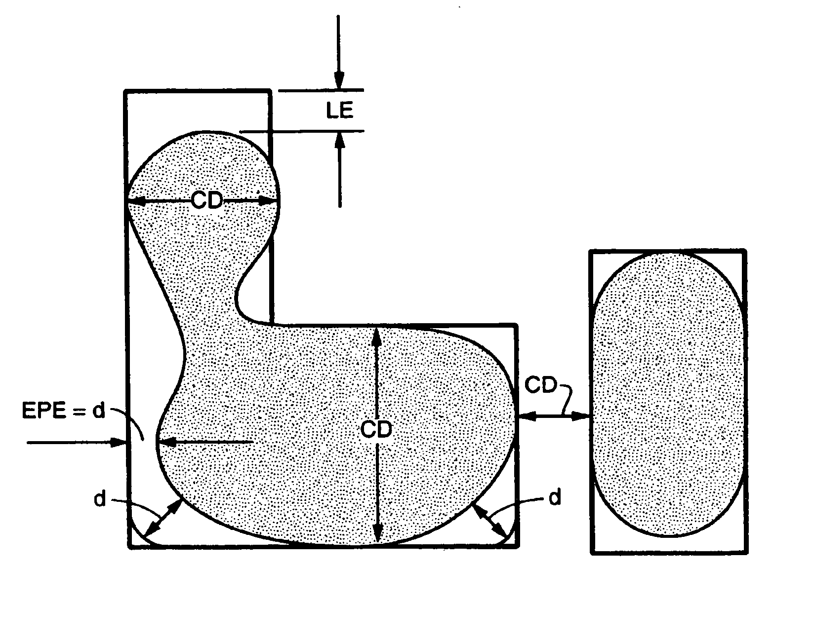
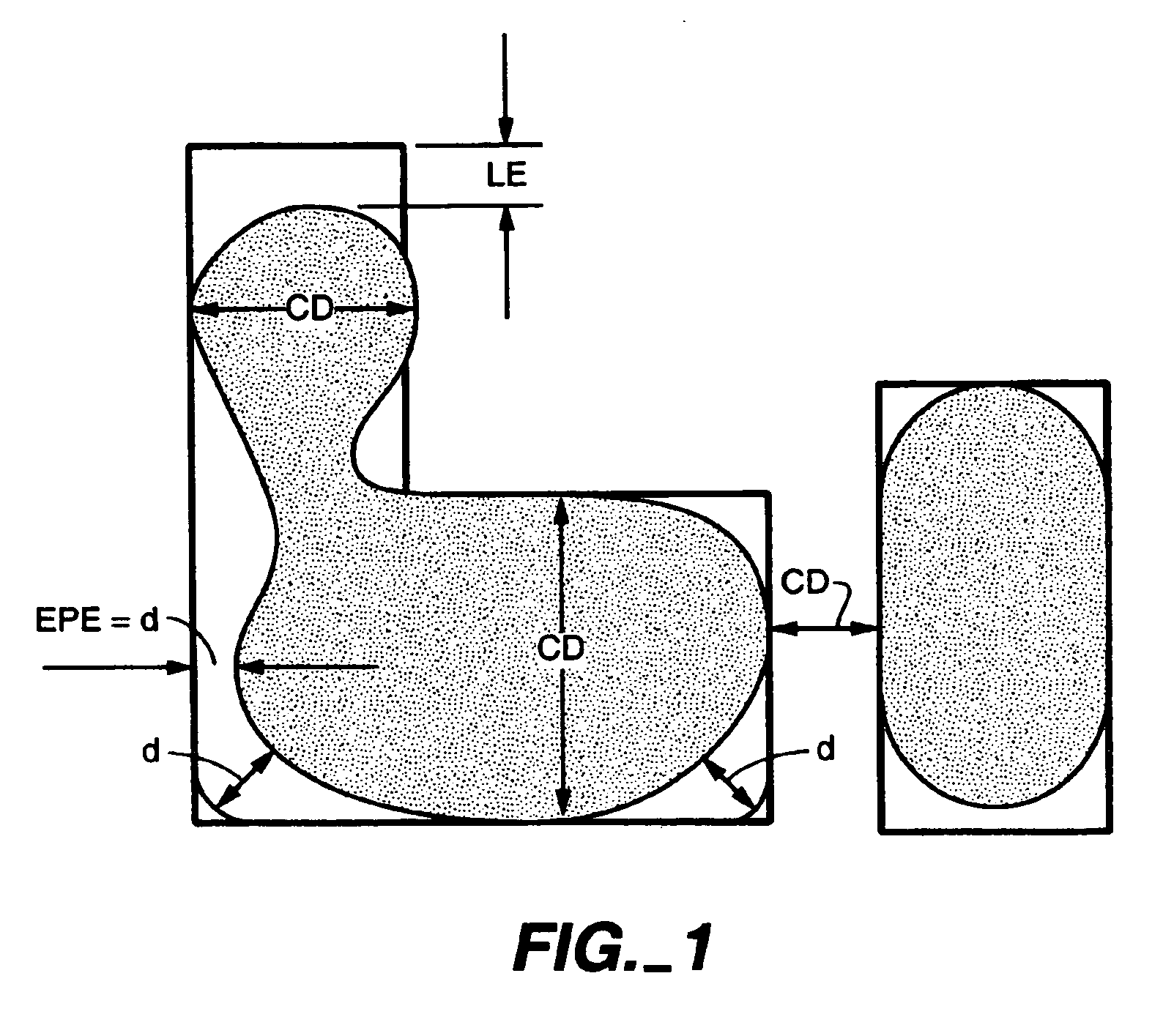
[0024]FIG. 1 illustrates an ideal boundary of a target design and a boundary of a simulated aerial image (shaded) providing post-OPC two dimensional quality definitions used in the description of the present invention. The aerial image represents substantially the optical information contained in the reticle pattern that is recorded in the photoresist layer of a semiconductor wafer. A simulated aerial image may be used for correcting mask pattern deviations resulting from optical proximity effects, and to find the locations in the reticle pattern that result in the worst case error.

[0025] Two-dimensional (2D) quality definitions and applications for post-OPC inspection are described more fully in U.S. patent application Ser. No. 10 / 155,620 filed May 22, 2002, titled “Quality Measurement of an Aerial Image” (hereinafter,...


PUM

PropertyMeasurementUnit
feature sizesaaaaaaaaaa
areaaaaaaaaaaa

Abstract

A method for performing post-optical proximity correction (OPC) multi layer overlay quality inspection includes the steps of generating a virtual target mask for a first mask and a second mask overlay using design rules at least partially defining the relationship between the first mask and the second mask; creating a composite aerial image representing a first mask image formed from the first mask and a second mask image formed by the second mask by performing imaging of the first mask and the second mask and overlaying the second mask image onto the first mask image; generating an overlay image map of the composite aerial image using the design rules at least partially defining the relationship between the first mask and the second mask; and comparing the overlay image map area and the virtual target mask area.

Description

CROSS-REFERENCE TO RELATED APPLICATIONS [0001] The present application is a continuation-in-part of U.S. patent application Ser. No. 10 / 155,620, filed May 22, 2002, which is herein incorporated by reference in its entirety. The present application is also related to U.S. Pat. No. 6,171,731, issued Jan. 9, 2001, which is herein incorporated by reference in its entirety.FIELD OF THE INVENTION [0002] The present invention generally relates to method for locating deviations from a pattern in a simulated aerial image, and more particularly, to a method of measuring the quality of a simulated multiple layer aerial image overlay. BACKGROUND OF THE INVENTION [0003] Photolithography is a common technique employed in the manufacture of semiconductor integrated circuit (IC) devices. Photolithography involves selectively exposing regions of a resist coated silicon wafer to a reticle (mask) pattern, and then developing the exposed resist in order to selectively process regions of wafer layers (e...

Claims


Application Information

Patent Timeline
Patent Type & Authority Applications(United States)
IPC IPC(8): G03F1/14G03F7/20G06T7/00
CPCG03F1/144G03F1/36G06T2207/30148G03F7/70666G06T7/001G03F7/705
Inventor CALLAN, NEALBELOVA, NADYA
Owner BELL SEMICON LLC
Why Eureka
Try Eureka