

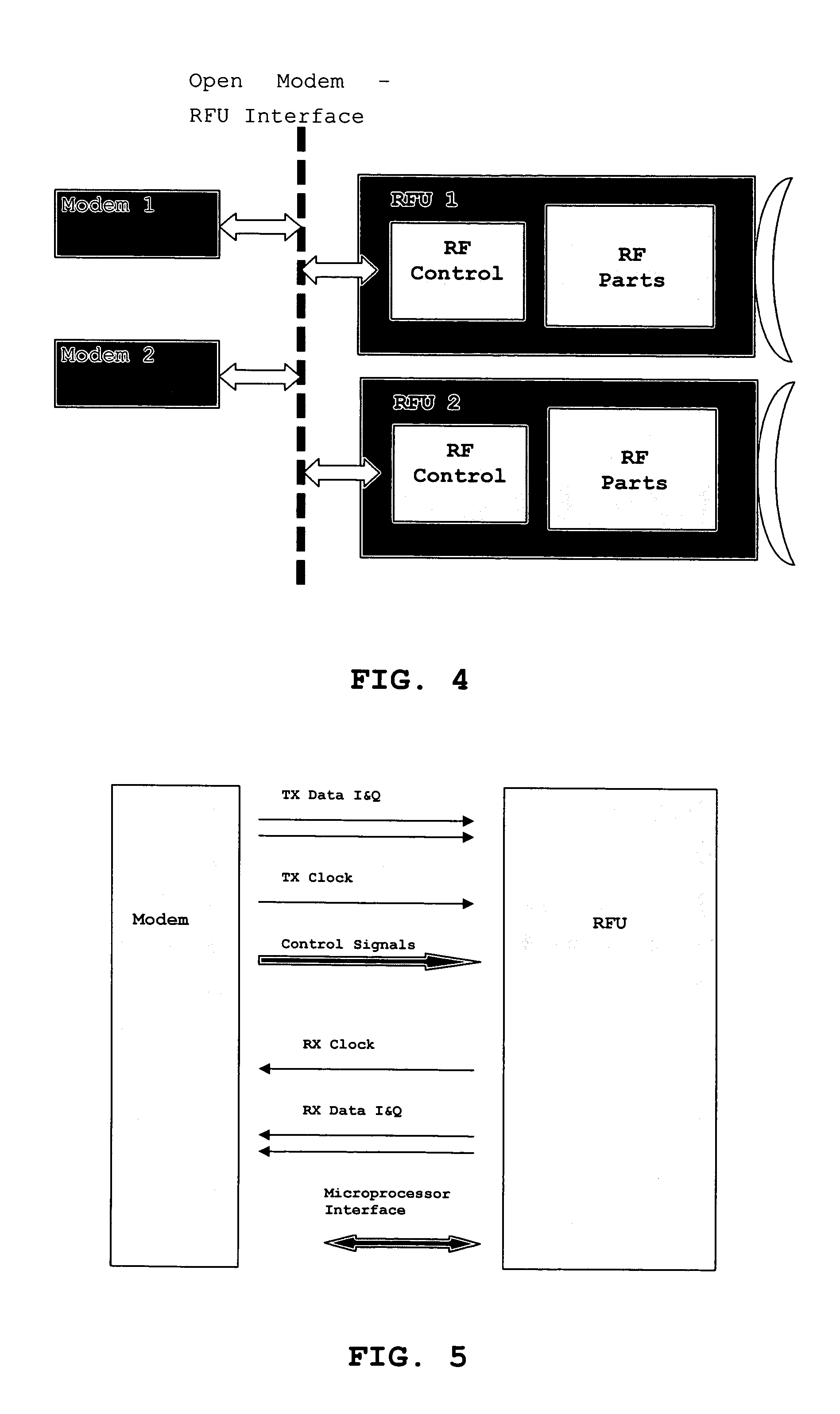
Open modem - RFU interface
a modem and interface technology, applied in the field of open modem rfu interface, can solve the problems of high design effort, inability to test radio frequency parts in product development phase, and inability to change the system in the normal way, and achieve the effect of more flexibility
- Summary
- Abstract
- Description
- Claims
- Application Information
AI Technical Summary
Benefits of technology
Problems solved by technology
Method used
Image

Examples
Embodiment Construction
[0041] In the present invention, some of the digital modem functions, which were previously implemented in the baseband (BB) modem, have been moved to the radio frequency control block in the radio frequency unit module. With the new interface, the functional split based on the modem function presentation given above between the baseband modem and radio frequency control block could be for example as presented in the following. Also other functional split alternatives are possible and covered by the present invention so that the following description is not intended to limit the present invention to the depicted embodiments.
Preferred Embodiment of the System
[0042] In the following, a preferred embodiment of the system according to the present invention is described. Accordingly, a new functional split is chosen as follows:
[0043] The baseband modem functionality comprises the functions of forward error correction (FEC) coding and decoding and symbol mapping and demapping.
[0044] ...
PUM
 Abstract
Description
Claims
Application Information