
Method of electron beam processing

a beam processing and electron beam technology, applied in the direction of electric beam welding apparatus, welding/soldering/cutting articles, manufacturing tools, etc., can solve the problems of process losing its advantages, serious process limitation, and very little distortion of the welding surface, and achieve the effect of reducing the diameter of the wir

Inactive Publication Date: 2005-05-19
DANMARKS TEKNISKE UNIV
View PDF7 Cites 12 Cited by
  • Summary
  • Abstract
  • Description
  • Claims
  • Application Information

AI Technical Summary

Benefits of technology

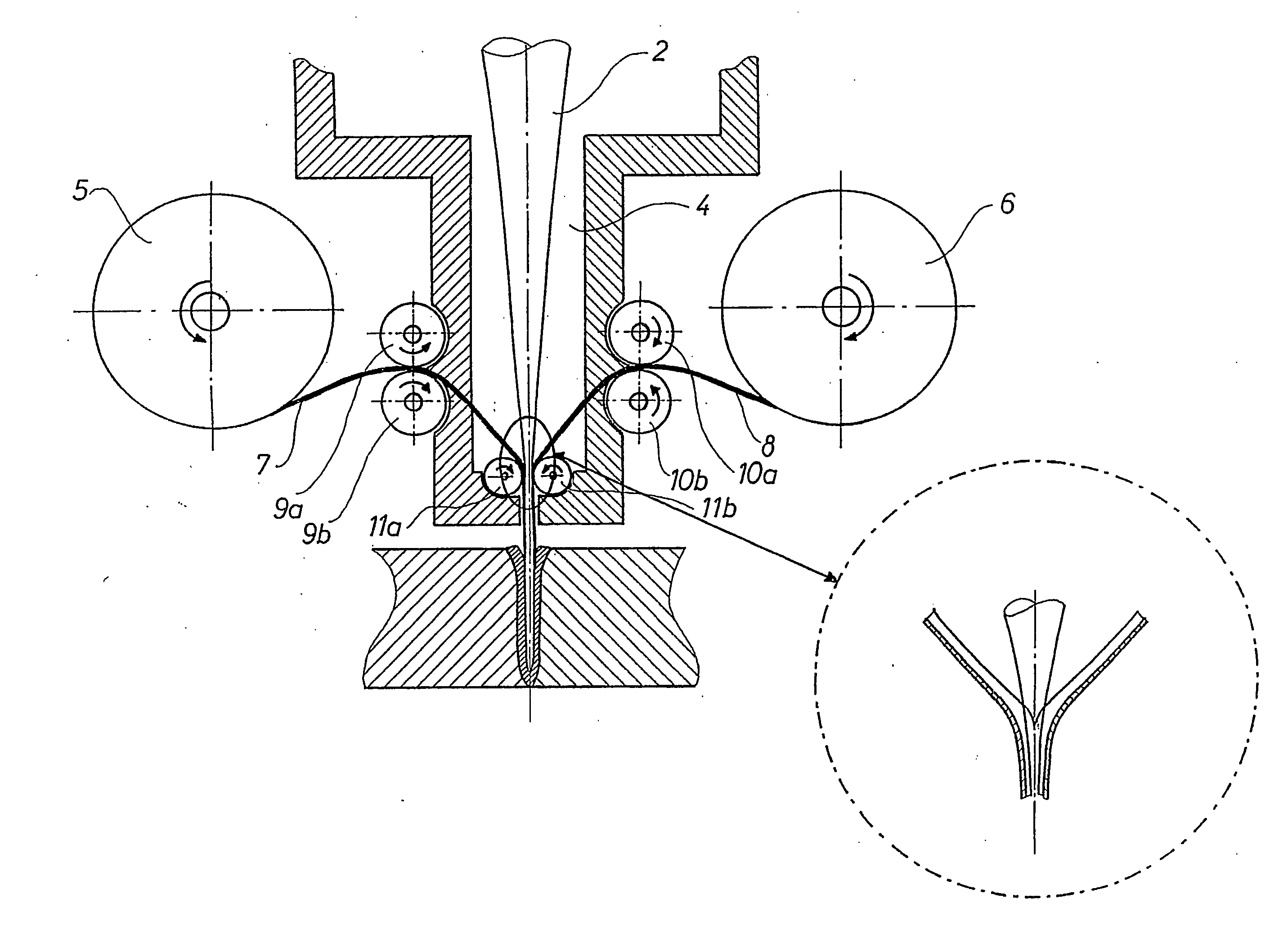
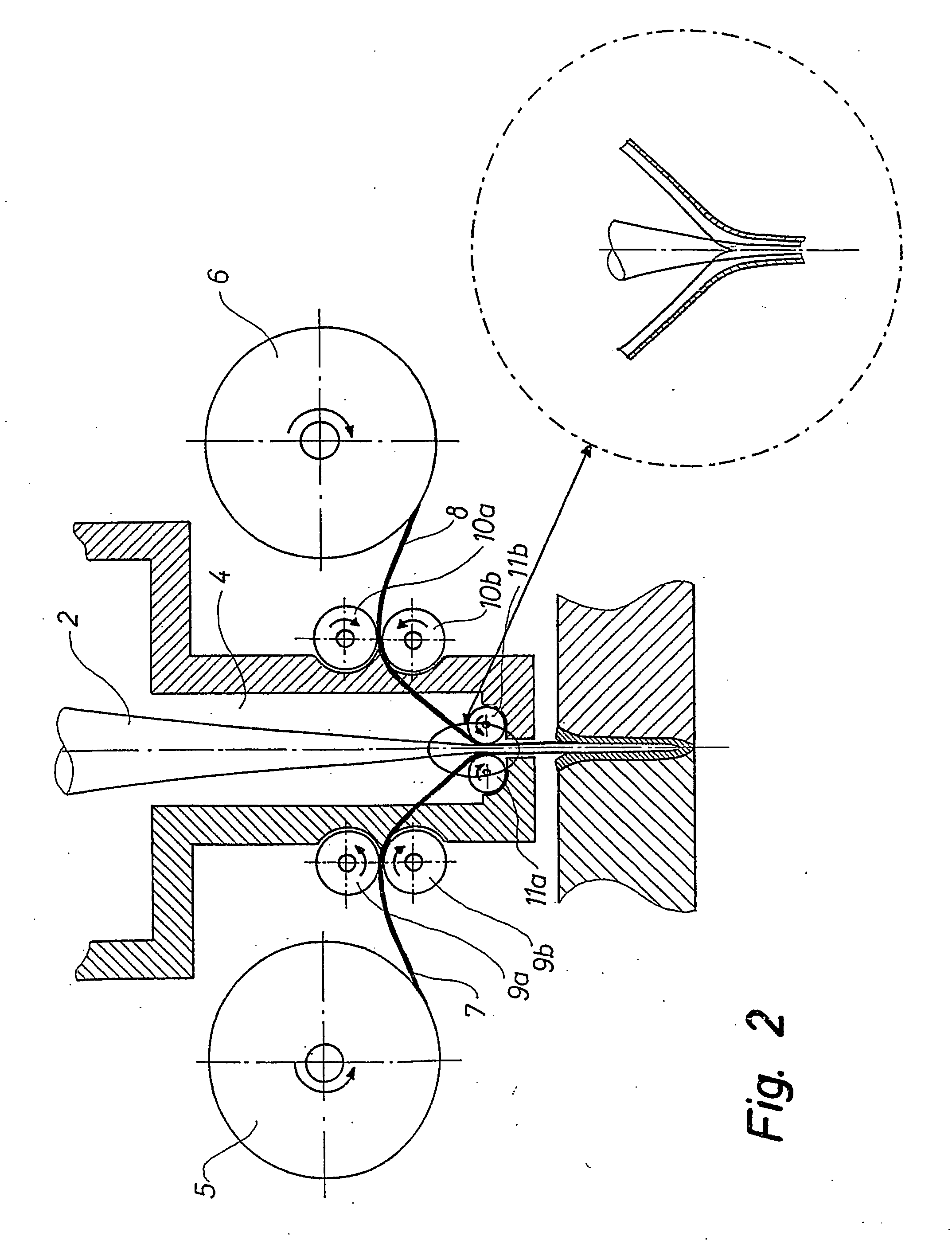
[0009] According to the invention, the seal can be provided by reducing the diameter of the wire by means of pressing or pulling the wire through an output opening of a matrix.

Problems solved by technology

This results in welds with very little distortion.
However, this means that the workpieces in question have to be placed in a vacuum chamber and have to be removed therefrom after welding.
This is time-consuming and a serious limitation of a process the greatest advantage of which is the option of welding workpieces of large thicknesses.
Although devices have been developed for electron beam welding under atmospheric pressure, these devices are disadvantageous in that the electron beam collides with molecules in the air thereby scattering the beam quickly and the process losing its advantages.

Method used


Image

  • Method of electron beam processing
  • Method of electron beam processing
  • Method of electron beam processing

Examples


first embodiment

[0029] the apparatus for carrying out the method according to the invention is shown in FIG. 2. The apparatus comprises a vacuum chamber 4 with an electron gun for generating the electron beam 2. A band 7 or 8 is fed into the vacuum chamber 4 from a roll 5 or 6 at different sides. The bands can be fashioned to form a wire by means of two sets of roller pairs, but the wire can also be formed prior to that. The latter results of course in certain problems caused by deformation of the wire when unwinding it from a roll and along the path to the welding point, but as the cross-section dimensions of the semicircular wires are relatively small, the above is possible, provided suitable care is taken in the design phase (not too small a curvature radius of the wire). If the bands are shaped by means of roller pairs 9a, 9b, 10a, 10b, their cross-section becomes semicircular, whereupon said bands are compressed and welded together inside the vacuum chamber by means of a roller pair 11a, 11b a...


PUM

PropertyMeasurementUnit
Thicknessaaaaaaaaaa
Pressureaaaaaaaaaa
Diameteraaaaaaaaaa

Abstract

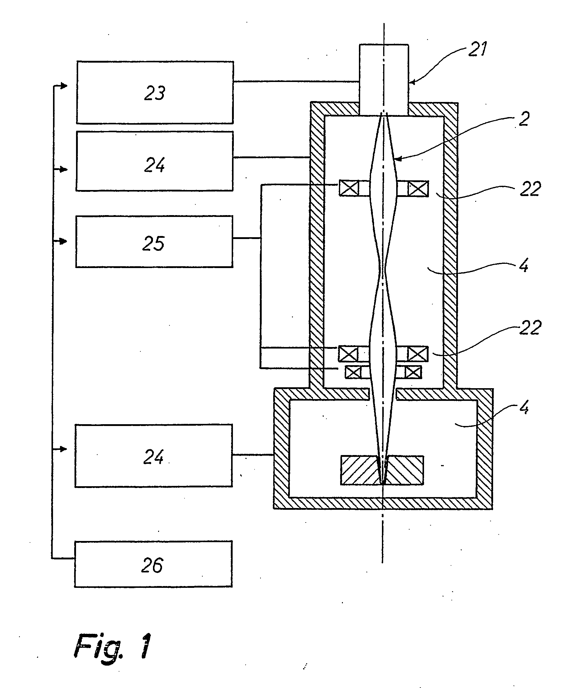
As a rule, electron beam welding takes place in a vacuum. However, this means that the workpieces in question have to be placed in a vacuum chamber and have to be removed therefrom after welding. This is time-consuming and a serious limitation of a process the greatest advantage of which is the option of welding workpieces of large thicknesses. Therefore the idea is to guide the electron beam (2) to the workpiece via a hollow wire, said wire thereby acting as a prolongation of the vacuum chamber (4) down to workpiece. Thus, a workpiece need not be placed inside the vacuum chamber, thereby exploiting the potential of electron beam processing to a greater degree than previously possible, for example by means of electron beam welding.

Description

TECHNICAL FIELD [0001] The present invention relates to a method of beam processing, preferably electron beam processing such as electron beam welding of a workpiece positioned outside a vacuum chamber wherein the electron beam is generated. BACKGROUND ART [0002] Electron beam welding can make very deep and narrow welds with minimum heat input to the workpieces to be welded. This results in welds with very little distortion. [0003] As a rule, electron beam welding takes place in a vacuum. However, this means that the workpieces in question have to be placed in a vacuum chamber and have to be removed therefrom after welding. This is time-consuming and a serious limitation of a process the greatest advantage of which is the option of welding workpieces of large thicknesses. [0004] Although devices have been developed for electron beam welding under atmospheric pressure, these devices are disadvantageous in that the electron beam collides with molecules in the air thereby scattering th...

Claims


Application Information

Patent Timeline
IPC IPC(8): B23K15/10
CPCB23K2201/32B23K15/10B23K2101/32
Inventor OLSEN, FLEMMING OVE
Owner DANMARKS TEKNISKE UNIV
Learn More