Vacuum furnace with pressurized intensive water quench tank

a technology of intensive water and vacuum furnace, which is applied in the direction of heat treatment equipment, furnaces, muffle furnaces, etc., can solve the problems of interrupting the intensive quenching process, and achieve the effects of increasing the boiling point of the quenching (water), uniform cooling, and intensive quenching process

Inactive Publication Date: 2005-05-19
IQ TECH
View PDF2 Cites 21 Cited by
  • Summary
  • Abstract
  • Description
  • Claims
  • Application Information

AI Technical Summary

Problems solved by technology

When the compressive stresses on the surfaces of the work-pieces are at a maximum and are at an optimum depth, or when the cooling recipes otherwise determine, the elevator in the quench tank lifts the work-pieces out of the quench tank and into the gas blanket above the tank, thus interrupting the intensive quenching process.

Method used


Image

  • Vacuum furnace with pressurized intensive water quench tank
  • Vacuum furnace with pressurized intensive water quench tank

Examples


Embodiment Construction

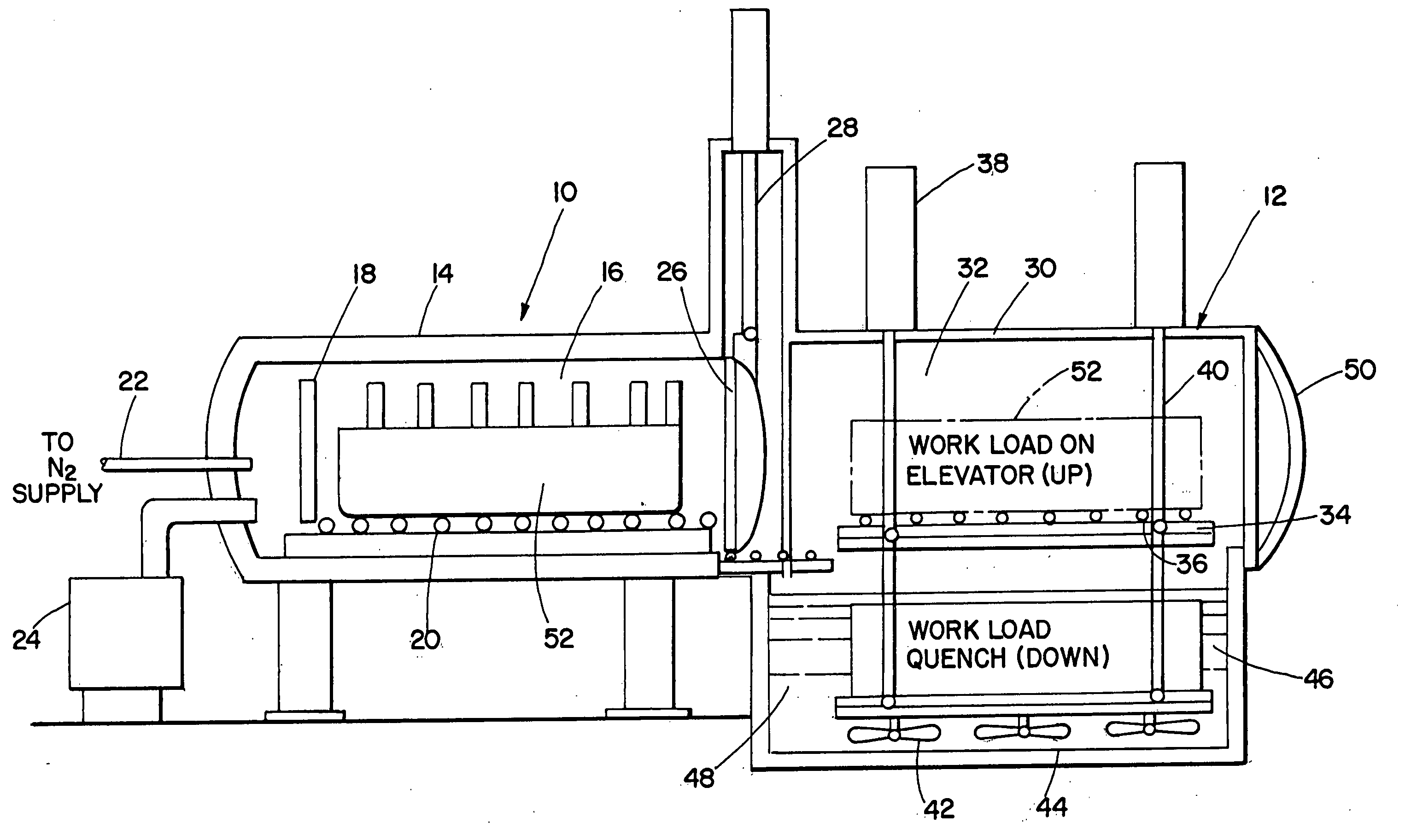
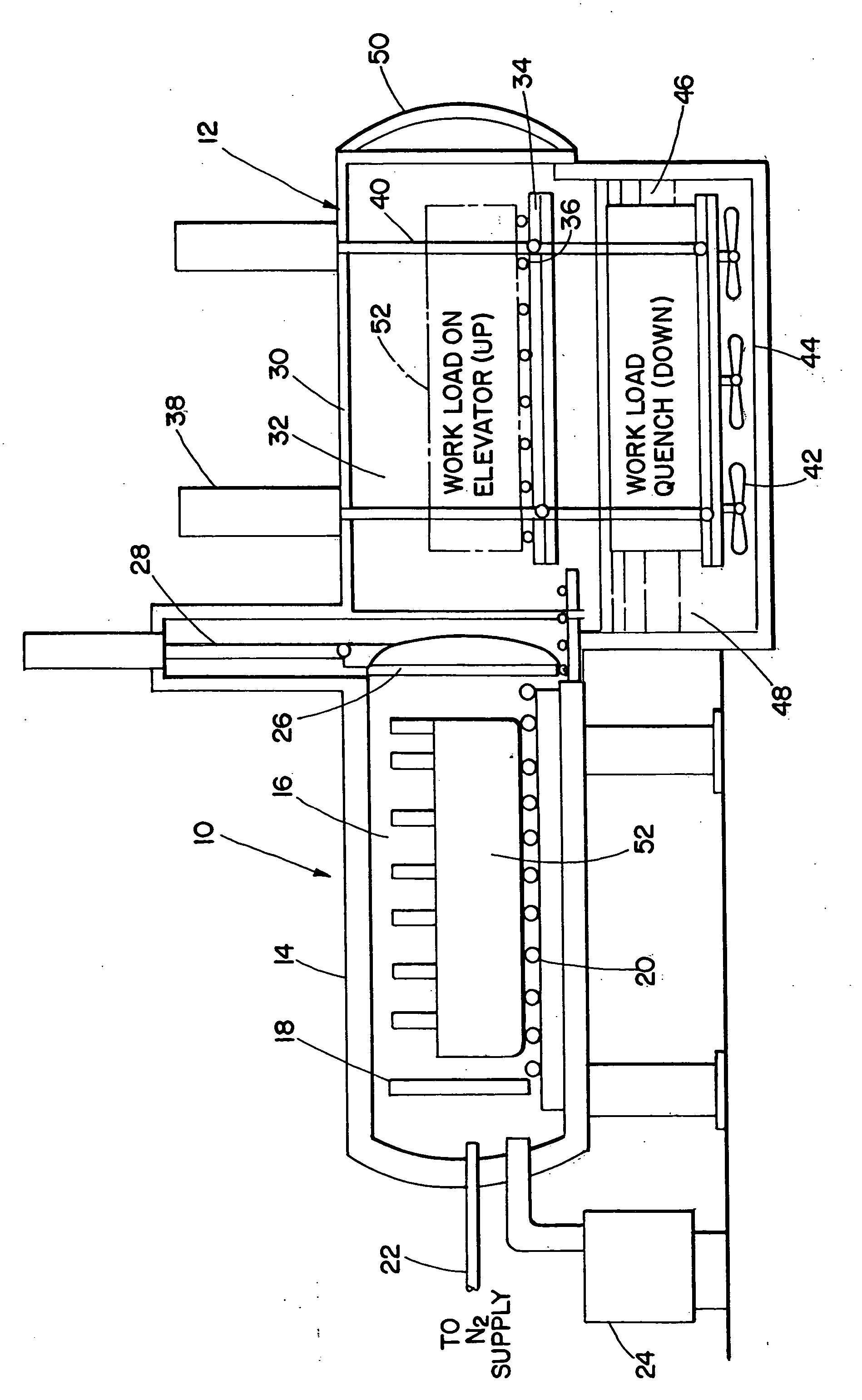
[0009] Referring now to the drawing where the illustration is for the purpose of describing the preferred embodiment of the invention and is not intended to limit the invention described herein, the single figure of the drawings is a front elevational view, broken away in cross-section, of the vacuum heat treating furnace 10 of the present invention having quenching apparatus 12 associated therewith. The furnace 10 includes an outer housing 14 that defines a heating chamber 16 having a plurality of heating elements 18 therein. It is understood that the quenching apparatus 12 can be physically separated from the heating chamber 16. A roller conveyor system 20 is provided within the heating chamber 16 to support the work-pieces to be heat treated. A source of nitrogen 22 and a vacuum pump 24 are provided to the heating chamber 16. An inner chamber vacuum door 26 separates the furnace 10 from the quenching apparatus 12. A door lifting device28 is provided to raise and lower the inner c...


PUM

PropertyMeasurementUnit
pressureaaaaaaaaaa
heataaaaaaaaaa
velocityaaaaaaaaaa

Abstract

A heat treating furnace having a quenching chamber incorporated therein or associated therewith is disclosed. The heating chamber within the furnace is utilized to heat work-pieces to a desired temperature. When the heating cycle has been completed, the heating chamber and the quenching chamber are back-filled with an inert gas to a redundant pressure (over atmospheric). The work-pieces are then transferred into the quenching chamber and lowered into the intensively agitated water in the water quench tank by an elevator mechanism. High quenchant (water) agitation rates eliminate film boiling on the surface of the hot work-pieces. When the compressive stresses on the surface of the work-pieces are at a maximum and are at an optimum depth, or when the cooling recipes otherwise determine, the elevator mechanism in the quenching chamber lifts the work-pieces out of the water quench tank and into the inert gas blanket above the tank, thus interrupting the intensive quenching process. The cores of the work-pieces are then allowed to cool uniformly by conduction through their intensively quenched outer shells. After cooling, the work-pieces, having both high hardness and low distortion, are removed from the quenching chamber.

Description

TECHNICAL FIELD [0001] The present invention relates, in general, to a vacuum heat treating device and, more particularly, to a vacuum heat treating furnace that has a pressurized intensive water quench tank incorporated therein or associated therewith. BACKGROUND ART [0002] Many existing vacuum furnaces utilize an oxygen-free gas quenching process. In such a gas quenching process, a fast moving and / or pressurized stream of gas extracts heat from the austenitized steel parts. Various gases, such as helium, nitrogen, argon, etc., or a mixture of thereof, are utilized for cooling purposes depending on the process requirements. In the case of a carbonaceous gas, low pressure (“vacuum”) carburize heating is done utilizing cyclohexane, nitrogen, methanol or endothermic gases. The work-piece cooling rate is dependent on the pressure and velocity of the cooling gas utilized. Gas quenching is utilized in those instances where quenching in still air is a very slow process and oil quenching i...

Claims


Application Information

Patent Timeline
Patent Type & Authority Applications(United States)
IPC IPC(8): C21D1/60C21D1/64C21D1/74C21D1/773F27B5/04F27B5/13F27B5/16F27D7/06F27D15/02
CPCC21D1/60C21D1/64C21D1/773C21D2241/01F27D15/02F27B5/13F27B5/16F27D7/06F27B5/04
Inventor KOBASKO, MYKOLA I.ARONOV, MICHAEL A.POWELL, JOSEPH A.
Owner IQ TECH
Why Eureka
Try Eureka