Gas generator and gas generant packet used therein

a generator and gas generant technology, applied in the direction of vehicular safety arrangments, pedestrian/occupant safety arrangements, vehicle components, etc., can solve the problems of reducing the performance variability of any inflator incorporating propellant, and achieve the reduction of the time required for assembling the inflator, the effect of reducing the weight of the inflator and reducing the performance variability of any inflator

Inactive Publication Date: 2005-05-19
JOYSON SAFETY SYST ACQUISITION LLC
View PDF4 Cites 4 Cited by
  • Summary
  • Abstract
  • Description
  • Claims
  • Application Information

AI Technical Summary

Benefits of technology

[0008] In yet another aspect of the invention, the invention includes a gas generant packet for use in a gas generator, wherein the packet includes a predetermined quantity of a gas generant sealed in a substantially gas-and-moisture-impermeable Mylar® container. Use of the moisture and gas impermeable container provides an improved method of assembly by ensuring that the same amount of propellant is included in each inflator. Furthermore, packaging of any one of the gas generants inhibits moisture retention during shipping or during storage of the respective gas generant prior to integration within an inflator. This is particularly useful for hygroscopic propellants, for example. Both advantages result in reduced performance variability of any inflator incorporating the propellant either due to propellant measurement fluctuations during propellant loading, or, due to propellant uptake of moisture given hygroscopic properties of the propellant and / or given humid conditions of assembly or storage.
[0009] The disclosed inflator structure provides several advantages over existing inflators. A wall of the container separates the gas generant enclosed in the container from any gas generant outside the container; thus, the body of the inflator need not incorporate structure for separating multiple quantities of gas generant. Also, the only structure required to withstand the forces produced by gas generant combustion is the combustion chamber itself. The weight of the inflator is thereby reduced.
[0010] In addition, by providing a pre-weighed gas generant charge enclosed in a container disconnected from the structure of the inflator, the time required to assemble the inflator is reduced. There is no need to measure a desired quantity of a gas generant at the gas generator assembly site, and there is no need to position the measured quantity of gas generant into a specially designed portion of the inflator structure. A container holding the pre-measured amount of gas generant is simply placed inside the combustion chamber between the igniter and another quantity of gas generant.
[0011] Any pre-determined quantity of a desired gas generant can be enclosed in the container. Also, as the container is substantially gas-and-moisture-impermeable, the gas generant may be chemically incompatible with a gas generant outside the container. The ability to concentrate pre-determined quantities of gas generant in desired location in the combustion chamber, and the ability to position one or more chemically incompatible gas generants in proximity inside the same combustion chamber, increase system flexibility and permit greater control of the system combustion profile.
[0012] Moreover, enclosing a gas generant charge in a container as described herein has been shown to attenuate the overall combustion profile of the gas generant system. Rather than an initially sharp spike of gas production, the most aggressive portion of gas production is deferred to a point later in the combustion profile. Consequently, an inflatable safety device deployed using a gas generator constructed according to the present invention will generally undergo the most aggressive portion of gas inflation at a point later in the device deployment process than would otherwise occur. The result is a smoother inflation of the inflatable cushion or airbag, resulting in a gradual inflation of the cushion and superior protection of the occupant in many instances.

Problems solved by technology

Both advantages result in reduced performance variability of any inflator incorporating the propellant either due to propellant measurement fluctuations during propellant loading, or, due to propellant uptake of moisture given hygroscopic properties of the propellant and / or given humid conditions of assembly or storage.

Method used


Image

  • Gas generator and gas generant packet used therein
  • Gas generator and gas generant packet used therein
  • Gas generator and gas generant packet used therein

Examples


Embodiment Construction

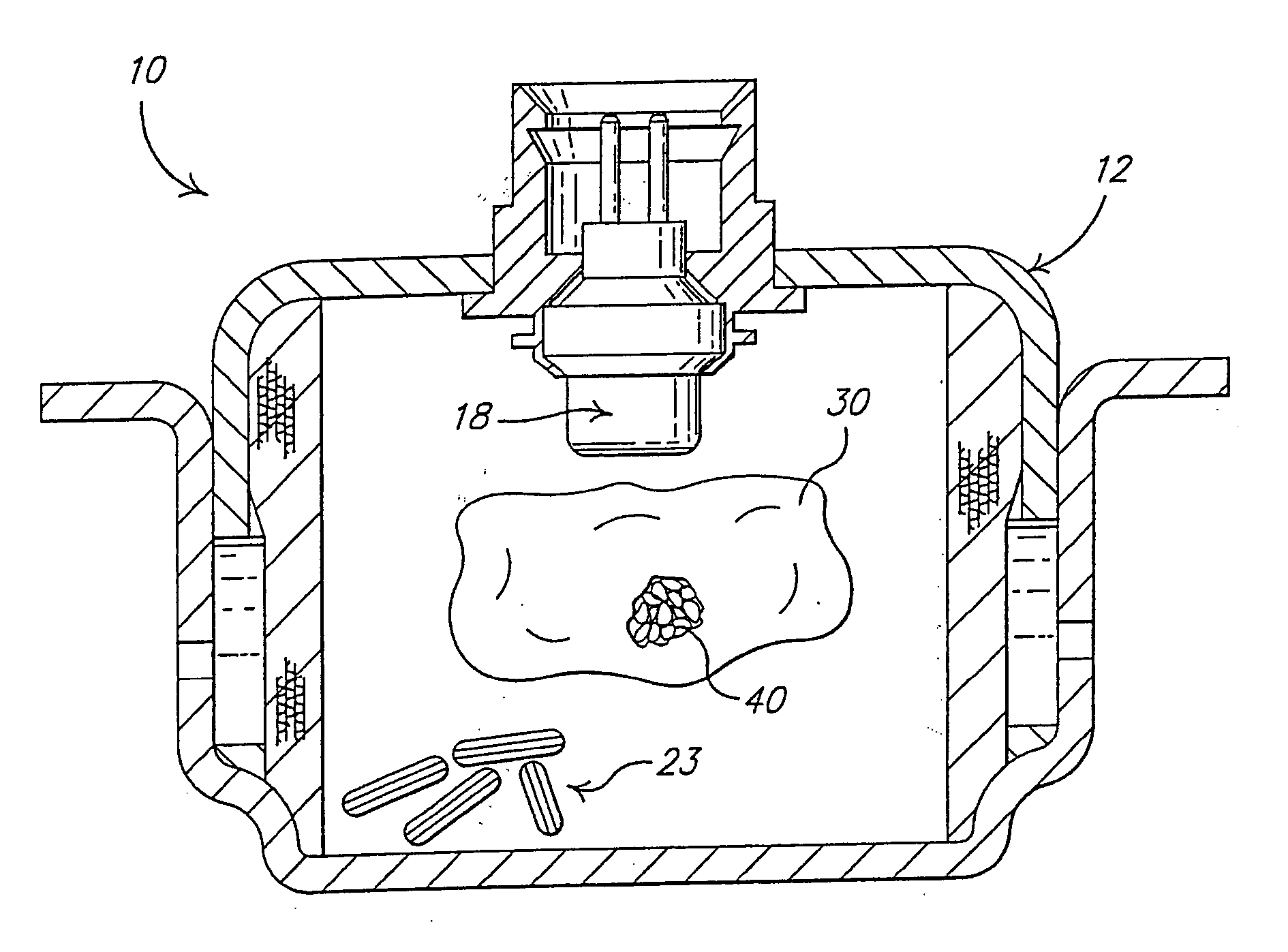
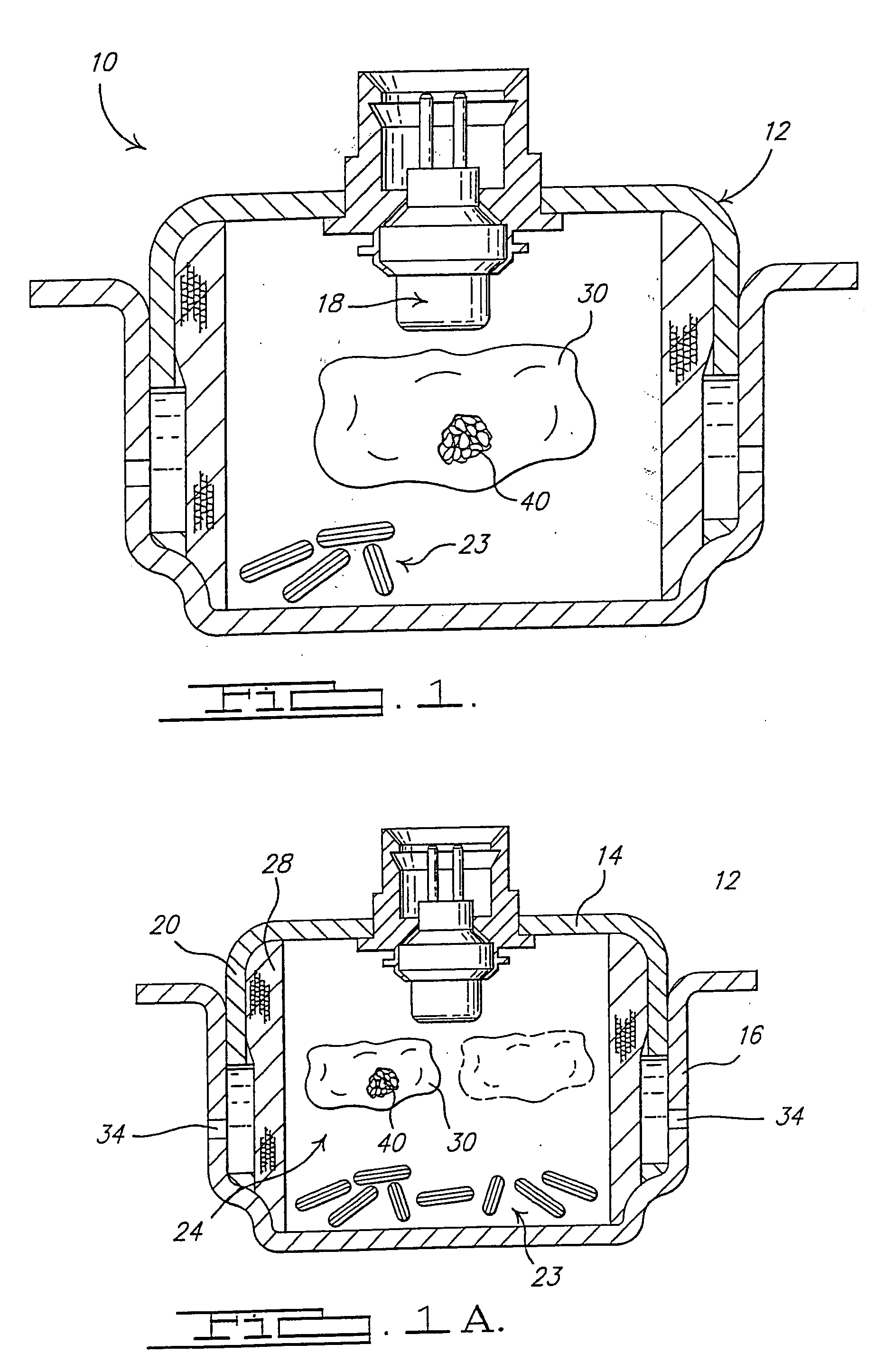
[0023]FIG. 1 shows one embodiment of a gas generator 10 in accordance with the present invention. Gas generator 10 is operable to supply pressurized gas to an inflatable safety restraint device of a vehicle occupant protection system, thereby protecting a vehicle occupant in the event of a crash or sudden deceleration.

[0024] In the embodiment shown, gas generator 10 includes a housing 12 having an upper housing portion 14 and a lower housing portion 16 secured to each other in a nested or abutting relationship using any of a variety of known methods, for example crimping, welding, adhesive bonding, or the application of fasteners. Housing 12 includes a peripheral wall 20 defining an interior combustion chamber 24 for receiving pre-determined amounts of one or more gas generant compositions therein, in a manner described in detail below.

[0025] One or more apertures 34 are formed in one or both of housing portions 14 and 16 to permit fluid communication between combustion chamber 24...


PUM


Abstract

A gas generator 10 and a gas generant packet 30 for use in an inflatable vehicle occupant protection system. The gas generator includes a housing 12, an igniter 18, and one or more gas generants 23 and / or 40 are positioned in a combustion chamber 24 defined by the housing 12. One or more of the gas generants 23 and / or 40 are enclosed in a substantially gas-and-moisture-impermeable container 30 disconnected from the housing 12, or suspended within the chamber 24, thereby forming pocket of gas generant therein. The container 30 may be formed from a polymer or polyester film. The gas generant packet may be variably positionable within the combustion chamber 24 prior to activation of the igniter 18. A method for manufacturing a gas generator 10 and a method for activating a gas generator 10 are also disclosed.

Description

CROSS-REFERENCE TO RELATED APPLICATION [0001] This application is entitled to and claims the benefit of Provisional Patent Application Ser. No. 60 / 498,715, filed on Aug. 28, 2003. BACKGROUND OF THE INVENTION [0002] The present invention relates generally to vehicle occupant protection systems, and more particularly to gas generators employed in occupant protection systems incorporating inflatable protection devices. [0003] Gas generators for use in inflatable vehicle occupant safety systems are well-known in the field of vehicle safety systems. Typically, such gas generators comprise a housing defining a combustion chamber, with a first, booster charge and a main gas generating charge positioned in the housing. An igniter, or squib, is also positioned in the housing to ignite the booster charge. Upon a crash event, combustion of the booster charge is typically initiated by providing an electrical signal to the igniter. Ignition of the booster charge induces ignition of the main char...

Claims


Application Information

Patent Timeline
Patent Type & Authority Applications(United States)
IPC IPC(8): B60RB60R21/26B60R21/264
CPCB60R21/2644
Inventor MCCORMICK, DAVID M.
Owner JOYSON SAFETY SYST ACQUISITION LLC
Why Eureka
Try Eureka