Reflective semiconductor optical amplifier light source

a technology of optical amplifiers and semiconductors, applied in the field of light sources, can solve the problems of inconvenient use of erbium-doped fiber amplifier light sources, and further difficulty in reducing manufacturing costs

Inactive Publication Date: 2005-05-19
SAMSUNG ELECTRONICS CO LTD
View PDF10 Cites 17 Cited by
  • Summary
  • Abstract
  • Description
  • Claims
  • Application Information

AI Technical Summary

Benefits of technology

[0012] A high-output RSOA light source is disclosed. The RSOA comprises a transmissive type semiconductor optical amplifier for creating and amplifying spontaneous emission light, a reflector for reflecting amplified spontaneous emission light outputted from the semiconductor optical amplifier such that amplified spontaneous emission light is reflected b...

Problems solved by technology

Although the erbium-doped fiber amplifier light sources produce stable high-power polarization-insensitive light, the produced wavelength band is limited so that the erbium-doped fiber amplifier light sources are unsuitable for the broadband light sources.
In addition, the size of the erbium-doped fiber amplifier light so...

Method used


Image

  • Reflective semiconductor optical amplifier light source
  • Reflective semiconductor optical amplifier light source
  • Reflective semiconductor optical amplifier light source

Examples


first embodiment

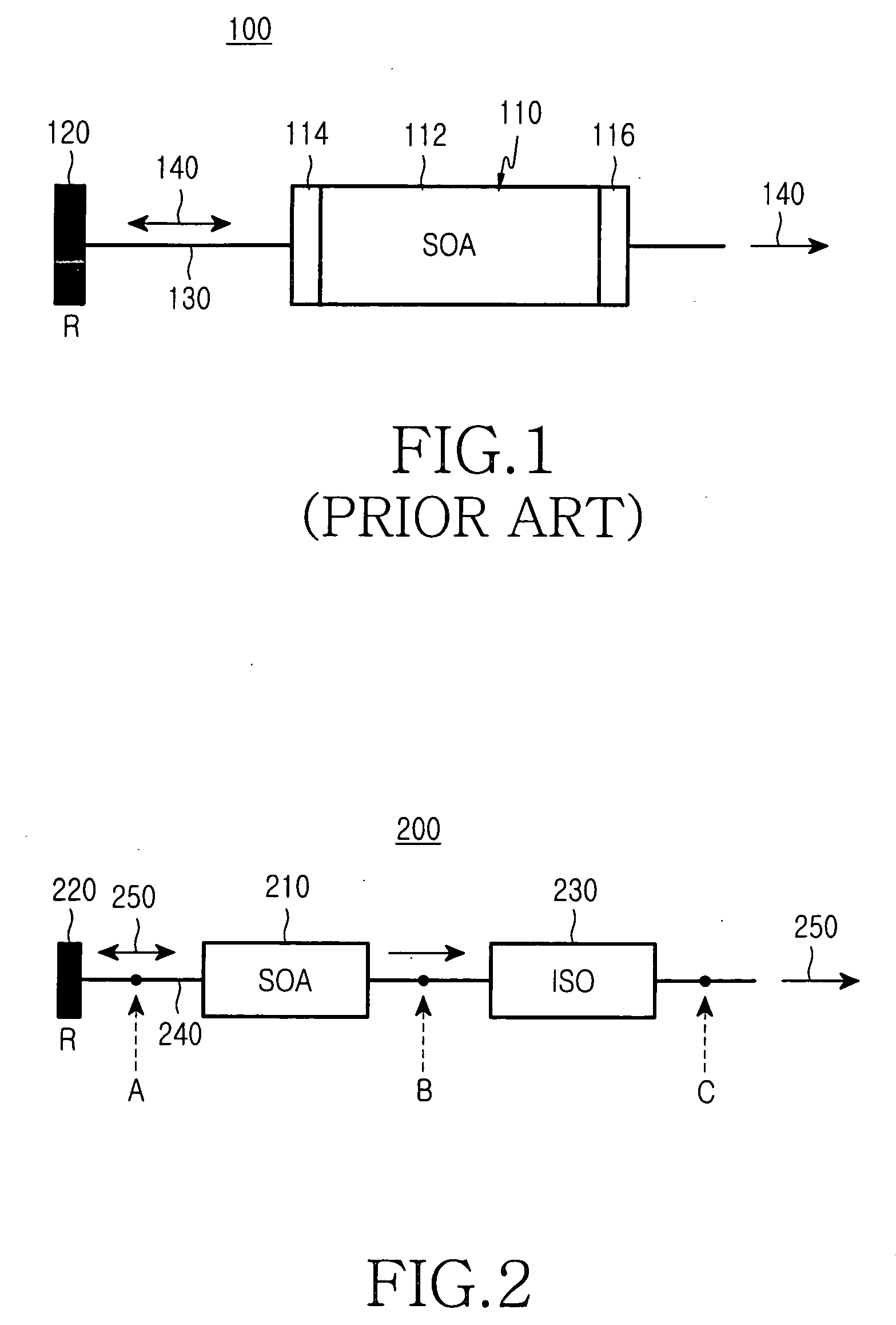
[0026]FIG. 4 is a schematic view showing a structure of a reflective semiconductor optical amplifier light source 400 according to the present invention. The reflective semiconductor optical amplifier light source 400 includes a semiconductor optical amplifier 410, a bandpass filter 420, a reflector 430, and an optical isolator 440.

[0027] The semiconductor optical amplifier 410 has a gain medium 412 and first and second anti-reflective layers 414 and 416 coated on both side ends of the gain medium 412, as previously described. Incoherent amplified spontaneous emission light 460 is outputted through the first and second anti-reflective layers 414 and 416. The reflector 430 is optically connected to the first anti-reflective layer 414, via optical medium 150, which reflects the incoherent amplified spontaneous emission light 460, back into the semiconductor optical amplifier 410. As discussed previously, the distance between the semiconductor optical amplifier 410 and the reflector 43...

second embodiment

[0030]FIG. 5 is a schematic view showing a structure of a reflective semiconductor optical amplifier light source 500 according to the present invention. The reflective semiconductor optical amplifier light source 500 includes a semiconductor optical amplifier 510 having a gain medium 512 and first and second anti-reflective layers 514 and 516 coated at both side ends of the gain medium 512, a reflector 540, a bandpass filter 520, a 45° polarization rotator (λ / 8) 530, and an optical isolator 550. The reflective semiconductor optical amplifier light source 500 is similar to the reflective semiconductor optical amplifier light source 400 shown in FIG. 4, with the inclusion of the 45° polarization rotator 530 located between the reflector 540 and the bandpass filter 520. Hence, only the 45° polarization rotator 530 needed be explained in detail to understand the embodiment shown in FIG. 5.

[0031] In this exemplary embodiment, 45° polarization rotator 530 is provided to improve the polar...

third embodiment

[0032]FIG. 6 is a schematic view showing a structure of a reflective semiconductor optical amplifier light source 600 according to the present invention. The reflective semiconductor optical amplifier light source 600 includes a semiconductor optical amplifier 610 having a gain medium 612 and first and second anti-reflective layers 614 and 616 coated at both side ends of the gain medium 612, a reflector 640, a bandpass filter 630, a 45° polarization rotator (λ / 8) 620, and an optical isolator 650. The reflective semiconductor optical amplifier light source 600 is similar to the reflective semiconductor optical amplifier light source 500 shown in FIG. 5, except that the 45° polarization rotator 620 is located between the semiconductor optical amplifier 610 and the bandpass filter 630. Again, only the operation of the 45° polarization rotator 620 in this position need be discussed to understand the operation of the embodiment shown in FIG. 6.

[0033] In this exemplary embodiment, amplifi...


PUM


Abstract

A reflective semiconductor optical amplifier light source is disclosed. The reflective semiconductor optical amplifier light source includes a transmissive type semiconductor optical amplifier for creating and amplifying spontaneous emission light, a reflector for reflecting amplified spontaneous emission light outputted from the semiconductor optical amplifier such that amplified spontaneous emission light is reflected back into the semiconductor optical amplifier, and a bandpass filter having a predetermined wavelength band width for limiting wavelength bands of the amplified spontaneous emission light capable of passing through the bandpass filter. In one aspect of the invention, the bandpass filter is interposed between the semiconductor optical amplifier and the reflector. In another aspect, a polarization filter is imposed to limit the reflected emission light to a predetermined polarization.

Description

CLAIM OF PRIORITY [0001] This application claims priority, pursuant to 35 U.S.C. §119, to that patent application entitled “Reflective Semiconductor Optical Amplifier Light Source,” filed in the Korean Intellectual Property Office on Nov. 18, 2003 and assigned Serial No. 2003-81474, the contents of which are hereby incorporated by reference. BACKGROUND OF THE INVENTION [0002] 1. Field of the Invention [0003] The present invention relates to a light source, and more particularly to a broadband light source for outputting Amplified Spontaneous Emission (ASE) light. [0004] 2. Description of the Related Art [0005] Erbium-doped fiber amplifier light sources, super luminescent diodes, and reflective semiconductor optical amplifier light sources have been suggested as broadband light sources for outputting incoherent light through wide wavelength bands. Although the erbium-doped fiber amplifier light sources produce stable high-power polarization-insensitive light, the produced wavelength ...

Claims


Application Information

Patent Timeline
IPC IPC(8): H01S5/50H01S3/00H01S5/00
CPCH01S5/005H01S5/0064H01S5/5018H01S5/50H01S5/0078H04B10/00
Inventor SHIN, DONG-JAELEE, JEONG-SEOKKIM, SEUNG-WOOHWANG, SEONG-TAEK
Owner SAMSUNG ELECTRONICS CO LTD
Why Eureka
Try Eureka