
Noise source synchronization for power spread signals

a power spread signal and noise source technology, applied in the field of electromagnetic interference and radiation emissions, can solve the problems of degrading graphics, and devices supporting high speed clocks and data paths, and affecting the quality of video, audio, and graphics

Inactive Publication Date: 2005-05-19
VIZIONWARE
View PDF32 Cites 18 Cited by
  • Summary
  • Abstract
  • Description
  • Claims
  • Application Information

AI Technical Summary

Benefits of technology

"The present invention relates to a method for reducing electromagnetic interference and radiated emissions in computer systems, communication devices, and advanced entertainment systems. The invention aims to overcome the limitations of existing techniques such as slowing down the clock, controlling rising and falling edges, utilizing Spread Spectrum Clock Generation (SSCG), and shielding. The method uses a spread digital clock signal and a pseudo random noise generator to achieve scalability and prevention of radiation problems. The invention also provides a power profile of frequency components to optimize the power distribution. Overall, the invention offers a more effective and scalable solution for reducing EMI and improving system performance."

Problems solved by technology

Increasingly, clock distribution has become an important issue in the design of computers, communication devices, and advanced entertainment systems as higher performance features / faster microprocessors are integrated into these systems.
However, devices supporting high speed clock and data paths are susceptible to internal and external radiation problems.
For example, computer, telecommunication, and entertainment systems have sensitive audio, video, and graphics circuitries, the performance of which can be affected by internal EMI radiation.
Furthermore, excessive internal EMI radiation degrades the quality of video, audio, and graphics, and causes system timing errors.
EMI concerns in external devices having high clock and data rates raise FCC (U.S. Federal Communication Commission) compliance issue problems, as these systems and devices often have electromagnetic interference (EMI) requirements.
While each of these EMI reduction techniques is effective to varying degrees, each also suffers attendant limitations.
For example, shielding requires the use of expensive conductive material to prevent emitted radiation from leaking outside of the shielded enclosure.
This, however, increases heat accumulation inside the computer, which can be exacerbated by reduced airflow or inadequate ventilation.
The other methods, slowing the clock, data rising and falling edges, and SSCG, all result in reductions in the timing margins, in addition to other problems.
Reductions of the timing margin are frequently undesirable for high-speed systems for which system timing is critical.
Timing requirements of systems implementing SSCG are further limited by the very jitter generated, based upon a frequency modulated analog signal, to reduce the EMI emissions.
Moreover, none of these EMI reduction methods is scalable.
That is, the EMI reduction cannot be programmed without adversely impacting system timings.
Furthermore, none of these methods wholly prevents radiation problems from occurring inside the computer.

Method used


Image

  • Noise source synchronization for power spread signals
  • Noise source synchronization for power spread signals
  • Noise source synchronization for power spread signals

Examples


Embodiment Construction

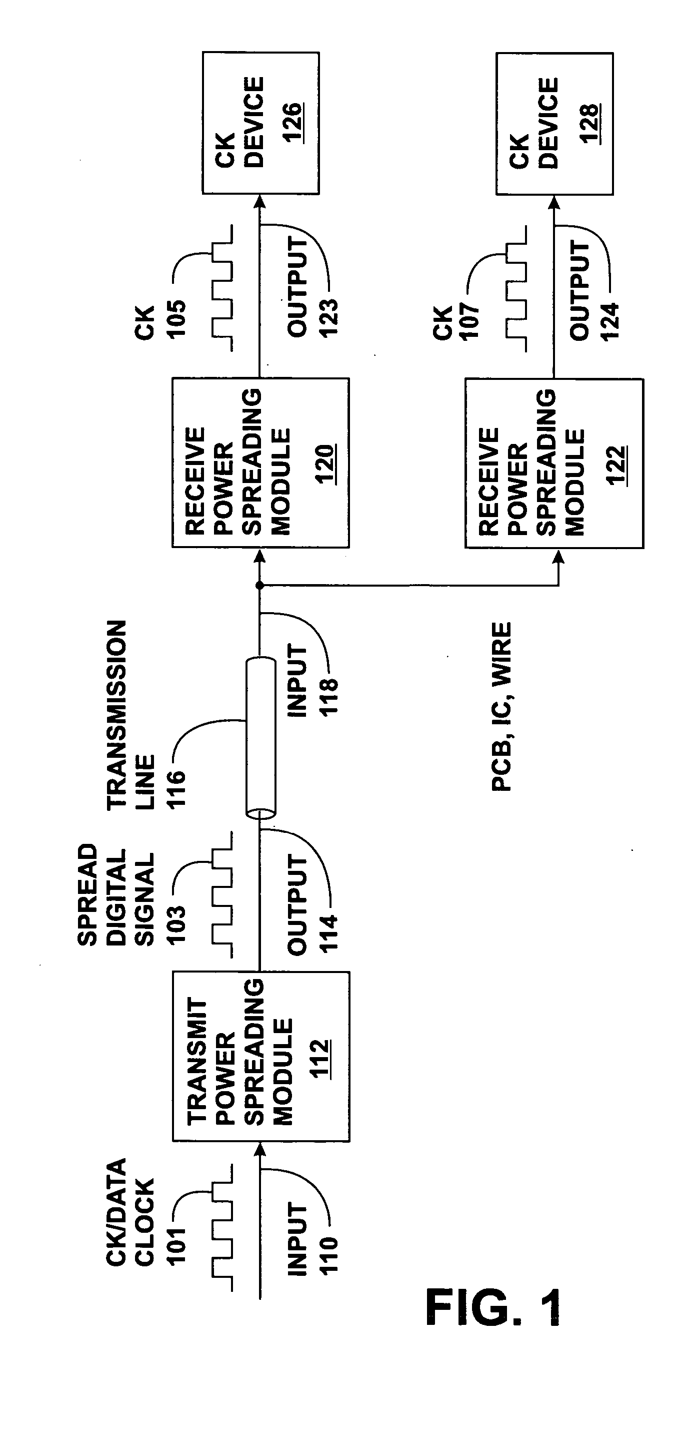
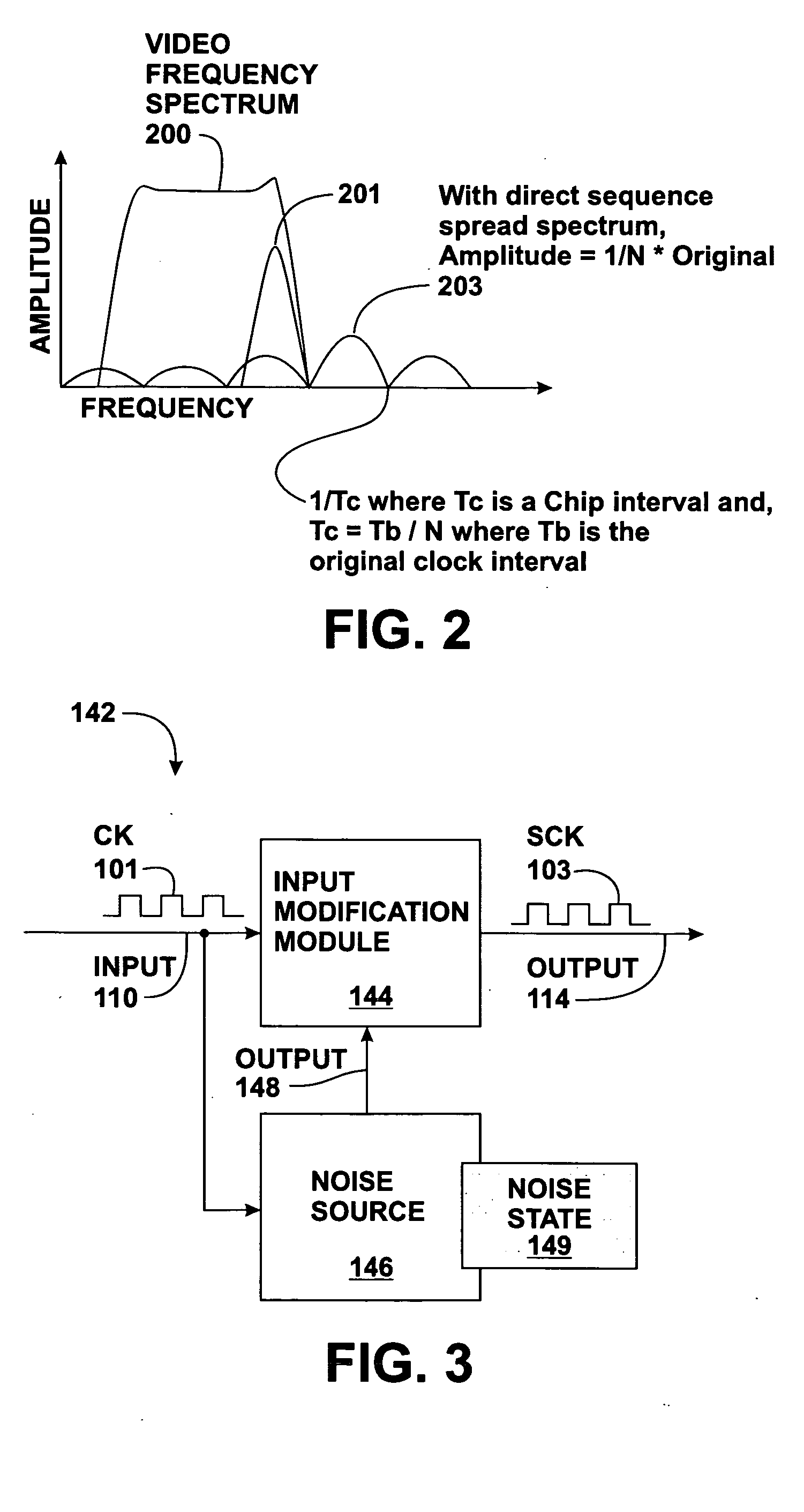
[0034] One embodiment of the present disclosure provides a method for a gated direct sequence spread spectrum (GDSSS) clock distribution in which an original clock signal or other digital data signal is divided and spread over a wider frequency spectrum to reduce the radiated emissions. As used herein, a clock is defined as integrated circuit based timing devices. In one embodiment, a clock signal is modified by a power spreading signal that introduces small phase shifts. These phase shifts may be random, pseudo-random, non-linear, based on a polynomial progression, and the like. Unlike with typical spread system solutions, these frequency hops, which spread the energy spectra (EMI), can occur at the frequency of the clock.

[0035] References to the term power spreading signal and the term noise source are made extensively herein. A power spreading signal (also referred to herein as a digital noise signal) comprises any of a variety of digital signals which is expected to introduce p...


PUM


Abstract

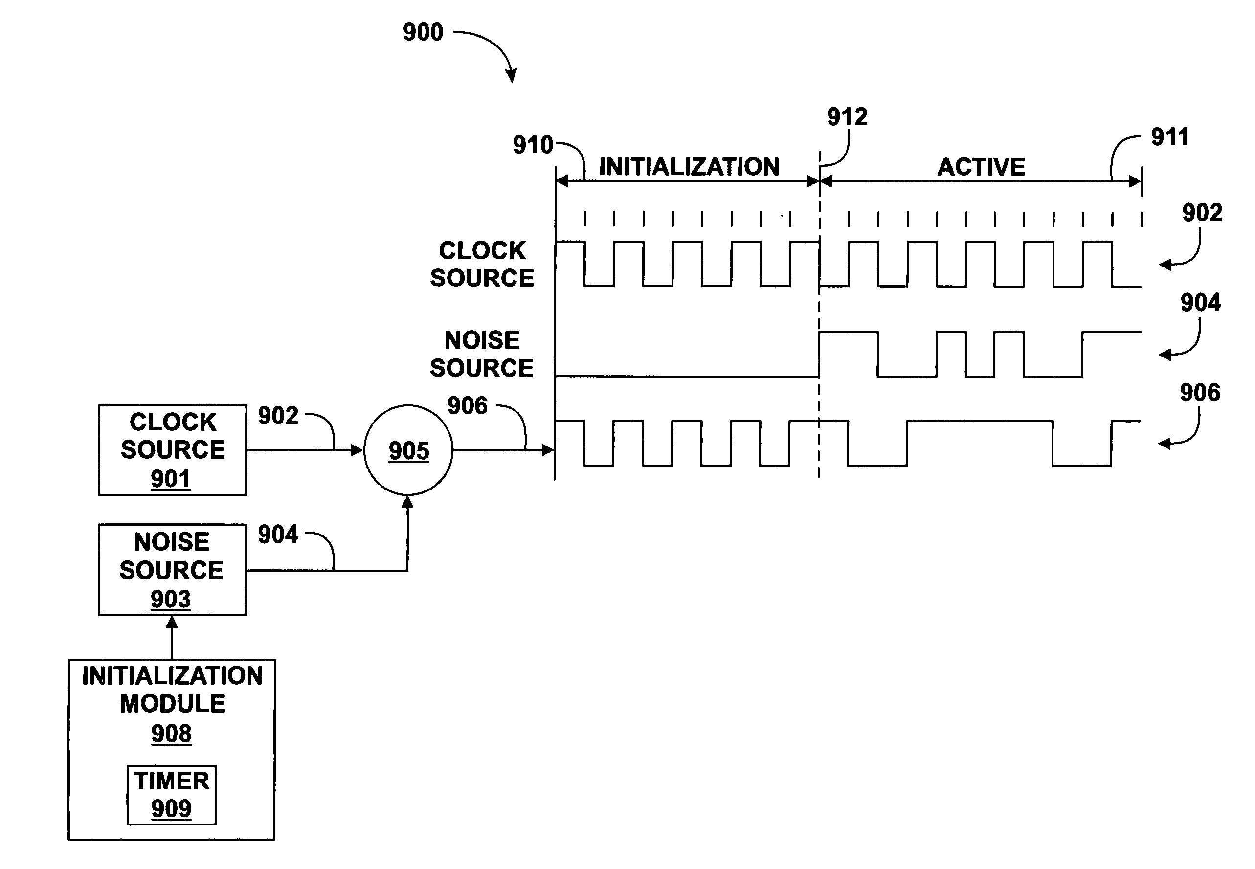
A method and system is disclosed for spreading the power associated with digital signals being transmitted to reduce electromagnetic interference (EMI) by operating a digital noise generator in an initialization state between a first time and a second time, operating the digital noise generator in an active state between the second time and a third time, modifying a digital clock signal based on an output of the digital noise generator, and providing the modified digital clock signal between the first time and the third time.

Description

CROSS-REFERENCE TO RELATED APPLICATIONS [0001] This application is a continuation-in-part application of U.S. patent application Ser. No. 10 / 357,255 filed on Feb. 3, 2003 and entitled “METHOD AND SYSTEM OF REDUCING ELECTROMAGNETIC INTERFERENCE” which claims priority to the following provisional applications: U.S. patent application Ser. No. 60 / 354,234 filed on Feb. 4, 2002, entitled “CLOCK DISTRIBUTION METHOD WITH PROGRAMMABLE RADIATED EMISSIONS REDUCTION”; U.S. patent application Ser. No. 60 / 365,330 filed on Mar. 18, 2002 and entitled “GATED DIRECT SEQUENCE SPREAD SPECTRUM CLOCK RECEIVER DESIGN”; U.S. patent application Ser. No. 60 / 365,348, filed on Mar. 18, 2002 and entitled “GATED PSEUDO-RANDOM (GPN) GENERATOR FOR CLOCK DISTRIBUTION APPLICATION”; and U.S. patent application Ser. No. 60 / 383,455, filed on May 25, 2002 and entitled “GATED DIRECT SEQUENCE SPREAD SPECTRUM CLOCK DISTRIBUTION SYSTEM AND METHOD FOR USING SAME,” the entireties of which are incorporated by reference herein...

Claims


Application Information

Patent Timeline
Patent Type & Authority Applications(United States)
IPC IPC(8): A63H3/28
CPCA63H3/28A63H2200/00
Inventor EGAN, KENNETH
Owner VIZIONWARE
Learn More