Signal transmission device

Active Publication Date: 2005-05-19
FUJIFILM BUSINESS INNOVATION CORP
View PDF1 Cites 77 Cited by
  • Summary
  • Abstract
  • Description
  • Claims
  • Application Information

AI Technical Summary

Benefits of technology

[0021] As described above, according to the present invention, the invention includes the excellent effects that power can be saved by shutting down the output of the optical signal when image information is not included in the electrical signal, the safety of the laser

Problems solved by technology

For this reason, cables (fiber cables, etc.) that convert high-speed signals to optical signals to realize long-distance transmission have also been proposed, but problems that must be resolved remain in terms of power consumption and safety in handling a laser light source for the optical signals.
For example, laser light is used in these optical transmission devices for emission light from the light source, but when there is unintentional cutting of the fiber cable or removal of the optical connector during operation, there is the potential for the laser light to leak to the outside and cause damage to human eyes.
However, with respect to cables in which optical fiber and electrical wiring are mixed together, problems remain in that, when cutting of the light is determined only by the connection status of the electrical wiring, the cutting cannot be

Method used


Image

  • Signal transmission device
  • Signal transmission device
  • Signal transmission device

Examples


first embodiment

(Overall Configuration)

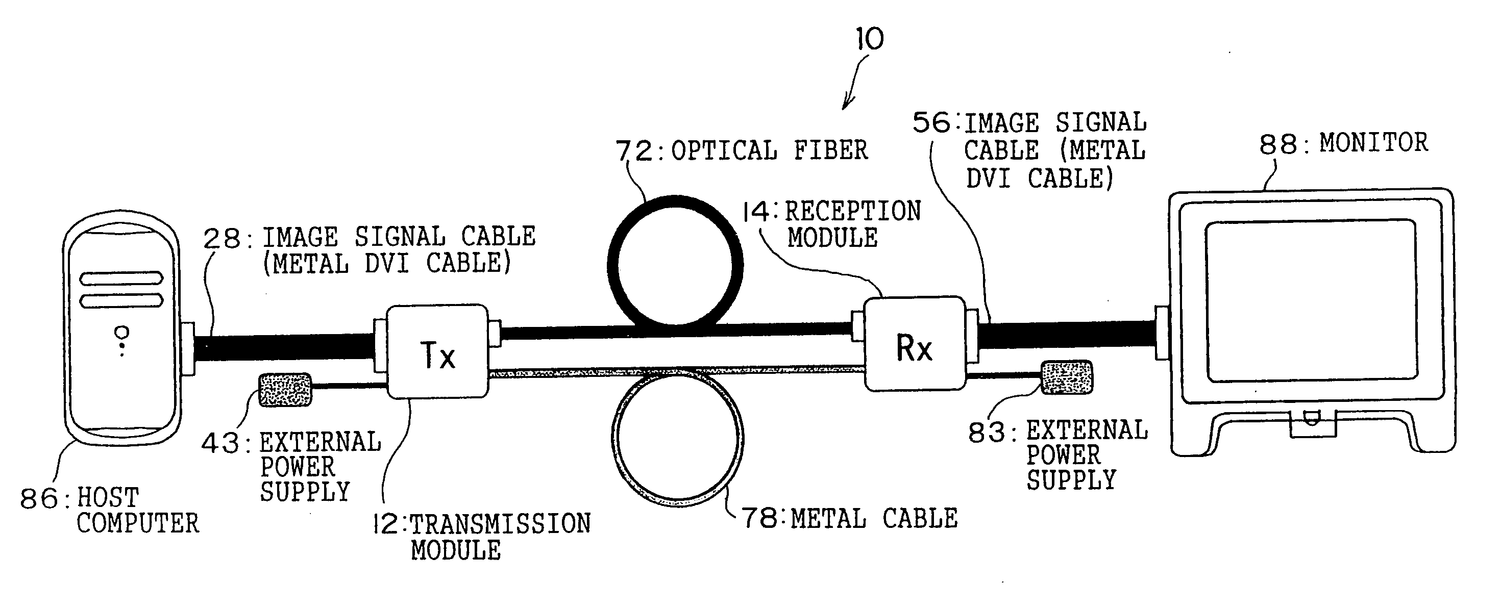
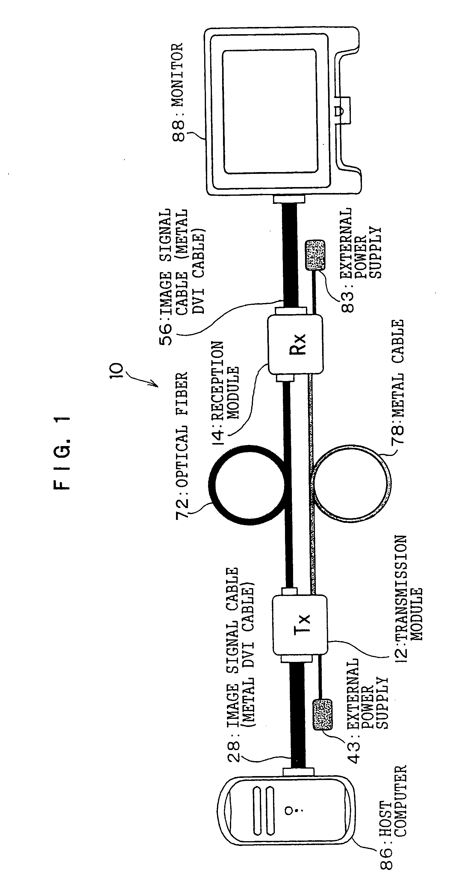
[0041] As shown in FIG. 1, an image signal transmission system pertaining to the present embodiment is configured by a host computer 86, a monitor 88, an optical transmission device 10, an image signal cable 28 that is a metal DVI cable connecting the host computer 86 to the optical transmission device 10, and an image signal cable 56 that is a metal DVI cable connecting the monitor 88 to the optical transmission device 10. The optical transmission device 10 is configured by a transmission module 12, a reception module 14, and an optical fiber cable 72 and a metal cable (electrical cable) 78 that connect the transmission module 12 and the reception module 78. External power supplies 43 and 83 are connected to the transmission module 12 and the reception module 14 in order to supply power from the outside.

[0042] The optical transmission device 10 of the present embodiment corresponds to a signal transmission device of the invention, the transmission module 1...

second embodiment

[0119] Next, a second embodiment of the invention will be described in detail. The present embodiment is for further reducing power consumption in regard to the reception module 14. Because the present embodiment has a configuration that is substantially the same as that of the preceding embodiment, the same reference numerals will be given to the same portions, detailed description of those same portions will be omitted, and the different portions will be described below.

(Electrical Configuration of the Transmission Module)

[0120]FIG. 14 shows the schematic electrical configuration of the transmission module 12 in the present embodiment. What is different from the configuration shown in FIG. 4 is that, here, a status output circuit 130 is added which outputs a Tx 5V signal used as a signal representing the power supply status when the external power supply 43 supplies power. The details will be described later, but an input side of the status output circuit 130 is connected to th...


PUM


Abstract

A transmission unit of a signal transmission device includes: a transmission-side detection unit that detects image information from an inputted electrical signal; a receiving unit that receives, from a reception unit, a status signal representing an arrival status of an outputted optical signal; and a control unit that controls an electrical-optical conversion unit on the basis of the detection result of the transmission-side detection unit and the status signal of the receiving unit so that the output of the optical signal is shut down in at least one of a case where image information is not included in an electrical signal and a case where an optical signal has not arrived.

Description

CROSS-REFERENCE TO RELATED APPLICATION [0001] This application claims priority under 35 USC 119 from Japanese Patent Application Nos. 2003-385961 and 2004-204184, the disclosures of which are incorporated by reference herein. BACKGROUND OF THE INVENTION [0002] 1. Field of the Invention [0003] The present invention relates to a signal transmission device, and in particular to a signal transmission device that uses optical signals. [0004] 2. Description of the Related Art [0005] In accompaniment with the increase in the resolution of liquid crystal panels and plasma displays, there is a demand to transmit, as digital signals, large-capacity image signals from a host. For example, in the Digital Visual Interface standard (DVI: a digital image transmission standard), which was established by the Digital Display Working Group (DDWG) that is an industry group, high-speed signals of 1.65 Gbps per 1 bit are transmitted using a differential signaling specification called transition minimized...

Claims


Application Information

Patent Timeline
IPC IPC(8): H04B10/00H04N7/22H04B10/03H04B10/07H04B10/25H04B10/524H04B10/54H04B10/80H04N21/61H04N21/647H04N21/6583
CPCH04B10/077H04B10/07955H04B10/504G09G2370/18G09G5/006G09G2370/12H04B10/564
Inventor OZEKI, SHINOBUKOBAYASHI, KENICHIYAMADA, HIDENORIKYOZUKA, SHINYANIITSU, TAKEHIROSUZUKI, KAZUHIROBABA, TOMOTAKANASHI, OSAMU
Owner FUJIFILM BUSINESS INNOVATION CORP
Why Eureka
Try Eureka