Peristaltic mixing and oxygenation system

Active Publication Date: 2005-05-19
MASSACHUSETTS INST OF TECH
View PDF9 Cites 26 Cited by
  • Summary
  • Abstract
  • Description
  • Claims
  • Application Information

AI Technical Summary

Benefits of technology

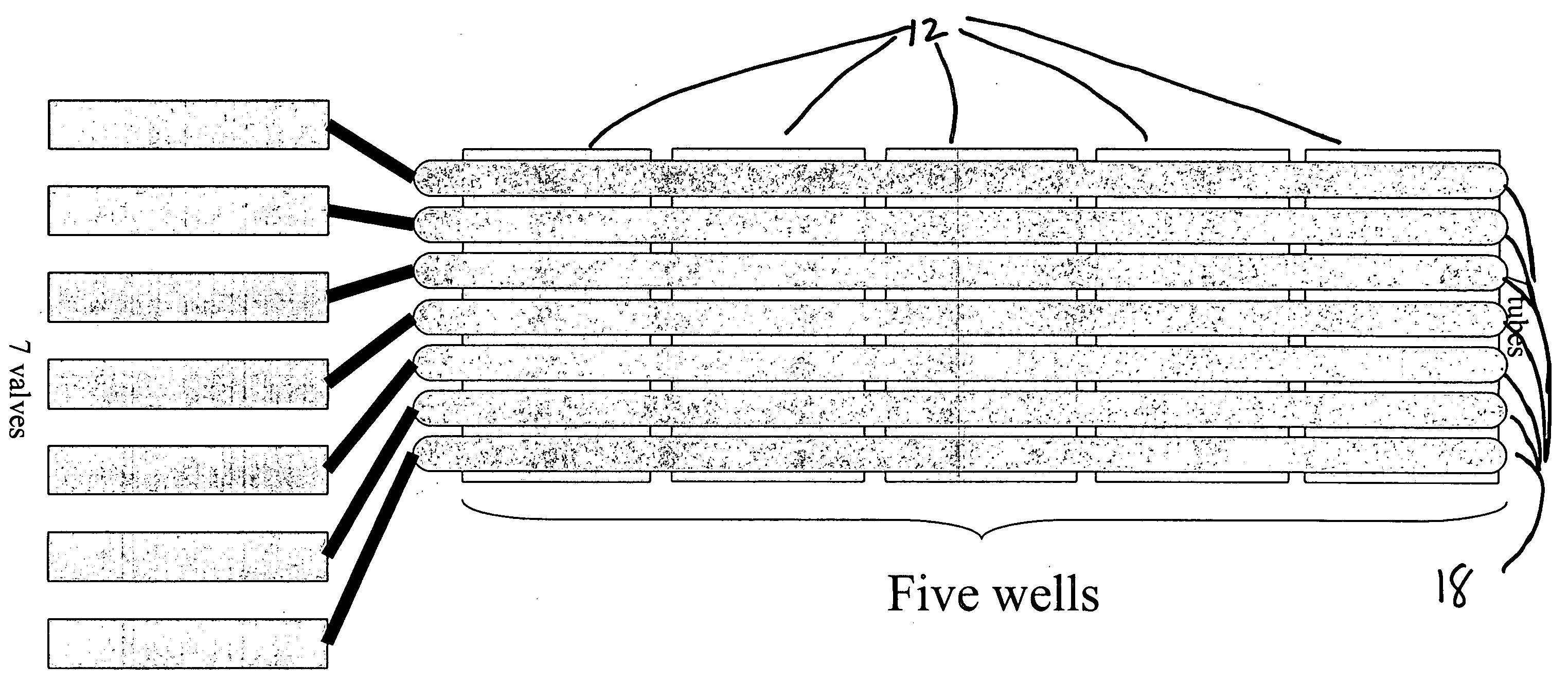
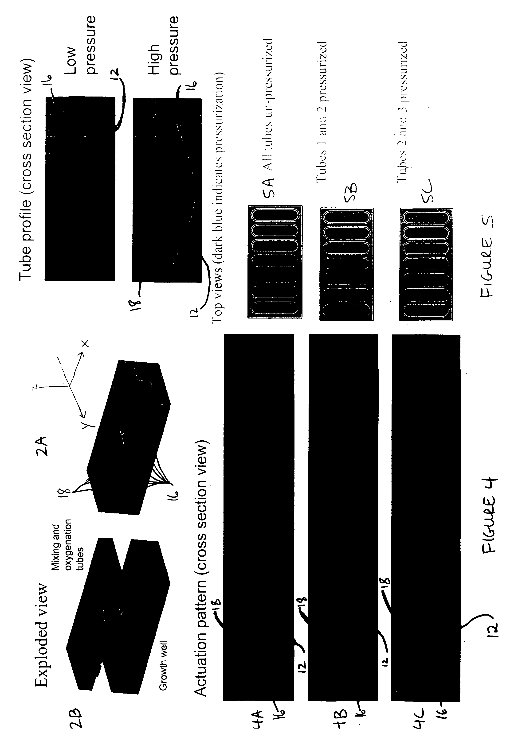
[0005] The present invention addresses this need, among others. In one aspect, the invention provides a device for fluid mixing and gas exchange comprising a housing defining a chamber for holding a liquid, wherein a wall of the chamber comprises a plurality of gas-permeable portions, and wherein the gas-permeable portions are selectively deflectable into the interior of the chamber. In certain embodiments of the invention the portions are deflectable by pressurizing a cavity in communication with the deflectable portion. In general, the cavities are pressurized using a gas or liquid having a higher concentration of a gas of interest (e.g., oxygen) than that in the chamber, e.g., from a high pressure reservoir. Pressurization of the cavities results in deflection of the deflectable portions into the chamber, thereby forcing the liquid inside to move and typically also pushes up the undeflected deflectable portions of the wall. In certain preferred embodiments of the invention the gas-permeable portions are deflected in a repetitive sequence that mixes and oxygenates the contents of the chamber by peristaltic action. In certain embodiments of the invention the device is fabricated as layers of an elastomeric structure. In other embodiments of the invention at least part of the housing is fabricated from glass, plastic, or metal, and a gas-permeable membrane forms the wall of the chamber having the deflectable portions. In certain embodiments of the invention multichamber devices are provided, in which each cavity contributes to the mixing and oxygenation of multiple chambers.

Problems solved by technology

Pressurization of the cavities results in deflection of the deflectable portions into the chamber, thereby forcing the liquid inside to move and typically also pushes up the undeflected deflectable portions of the wall.

Method used


Image

  • Peristaltic mixing and oxygenation system
  • Peristaltic mixing and oxygenation system
  • Peristaltic mixing and oxygenation system

Examples


Embodiment Construction

[0040] I. Overview

[0041] Development of small scale bioreactors must take a number of considerations into account. In general, the minimum size of conventional bioreactors is related to the desire for modularity that can be achieved by using industry standard dissolved oxygen and pH probes, which are typically 0.5 inches in diameter and 6-8 inches long, and industry standard mixing technology to support oxygenation. This typically requires growth chambers large enough to support high Reynolds number turbulent flows and electric motors with adequate torque at high angular velocity. In general, the Reynolds number of a fluid flow describes its flow regime, e.g., laminar or turbulent flow (Beebe, D. J., Mensing, G. A., and Walker, G. M., “Physics and applications of microfluidics in biology”, Annu. Rev. Biomed. Eng., 4:261-86.). Turbulent flow is chaotic and unpredictable (i.e., it is generally not possible to predict the position of a particle in the fluid stream as a function of tim...


PUM

PropertyMeasurementUnit
volumeaaaaaaaaaa
volumeaaaaaaaaaa
volumeaaaaaaaaaa

Abstract

The present invention provides devices and methods for achieving mixing and gas exchange in chambers having a small volume. According to the invention a chamber includes one or more walls that are made of a gas-permeable material and that include multiple portions that are selectively deflectable into the interior of the chamber. The deflectable portions are in communication with a hollow cavity or space that can be pressurized. Pressurization results in deflection of the deflectable portion into the chamber. Pressurization is achieved using a gas or fluid that contains a gas of interest such as oxygen. The portions are deflected in a sequence that results in peristaltic action that mixes and oxygenates the contents of the chamber. In a preferred embodiment of the invention the hollow cavities are an assembly of tubes that deflect into a plurality of chambers. A particular use for the invention is as a culture vessel for cells such as bacteria.

Description

BACKGROUND OF THE INVENTION [0001] A large number of useful substances are most efficiently produced by microorganisms such as bacteria or fungi (Shuler, M. L. and Kargi, R., Bioprocess Fundamientals (2nd Ed.), Prentice Hall (2001); Doran, P., Bioprocess Engineering Principles, Academic Press (1995)). This includes some pharmaceutical products, food additives and supplements, bulk chemicals such as ethanol, and enzymes. While organisms that produce the desired substance may occur in nature, their metabolism is likely not optimized to produce the desired product, and harvesting product from microorganisms as they exist in nature is frequently not practical. In addition, an increasing number of useful products including a variety of pharmaceutical agents (e.g., antibodies, enzymes) are produced by harvesting them from mammalian cells or culture medium. Bioprocess development typically involves improving the microorganism or cell (e.g., through selection, mutation, or recombinant DNA t...

Claims


Application Information

Patent Timeline
Patent Type & Authority Applications(United States)
IPC IPC(8): B01F11/00B01F13/00
CPCB01F11/0045B01F13/0059B01F2215/0431C12M23/40C12M23/24C12M23/26B01F2215/0454B01F31/31B01F33/30
Inventor LEE, HARRY
Owner MASSACHUSETTS INST OF TECH
Why Eureka
Try Eureka