High flow-low pressure irrigation system

a low-pressure irrigation and high-flow technology, applied in the field of renal cooling systems, can solve the problems of obscuring the surgical field of view, exposing the surrounding structures, and complex renal surgery that often requires transient interruption of the renal vasculature, and achieves the effect of convenient deploymen

Active Publication Date: 2005-05-19
APPL MEDICAL RESOURCES CORP
View PDF9 Cites 102 Cited by
  • Summary
  • Abstract
  • Description
  • Claims
  • Application Information

AI Technical Summary

Benefits of technology

[0007] The present invention is directed to a high-flow low-pressure irrigation system for directing a fluid to and recovering the fluid from an area within a body. The irrigation system comprises a sheath defining a sheath lumen and a flexible catheter disposed in and through the sheath lumen. The flexible catheter defines a catheter lumen and comprises a plurality of apertures at a distal portion that extends beyond the sheath lumen and spreads in the body area. The fluid is directed and outputted to the body area through the catheter lumen and the apertures, and the outputted fluid is recovered and returned through the sheath lumen. The irrigation system can be endoscopically placed inside a body cavity such as the kidney prior to laparoscopic surgery. The fluid may be a cooling solution such as saline, which is introduced to the irrigation system to allow for preservation of renal tissue during renal artery clamping. A feature of the invention is that only the lumen being irrigated, the catheter lumen, is exposed to the fluid or cooling solution. An advantage of the system of the invention is the fluid or cooling solution can be delivered directly to a very defined space via the catheter lumen while the pressure is kept low by the sheath recovering the outputted fluid. In a renal application, for example, the catheter lumen can deliver the cooling solution directly to the collecting system of the kidney as the access sheath tamponades the ureter and the bladder is completely bypassed. Another feature of the invention is it can be made as a one-piece system that can be easily deployed.

Problems solved by technology

Complex renal surgery frequently requires transient interruption of the renal vasculature.
Although this practice provides sufficient cooling of the kidney, it presents many drawbacks such as exposing the surrounding structures to the cooling effects of the ice or slush and obscuring the surgical field of view by the ice or slush.
Moreover, the practice of packing the kidney in ice or slush is not feasible for minimally invasive or laparoscopic surgery.
With growing interest in laparoscopic surgery, the inability to achieve renal hypothermia during laparoscopic surgery has become a significant problem.

Method used


Image

  • High flow-low pressure irrigation system
  • High flow-low pressure irrigation system
  • High flow-low pressure irrigation system

Examples


first embodiment

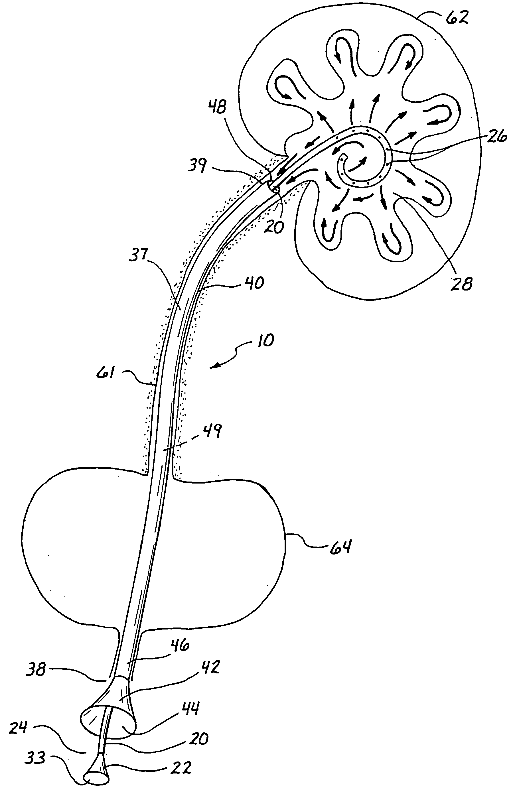
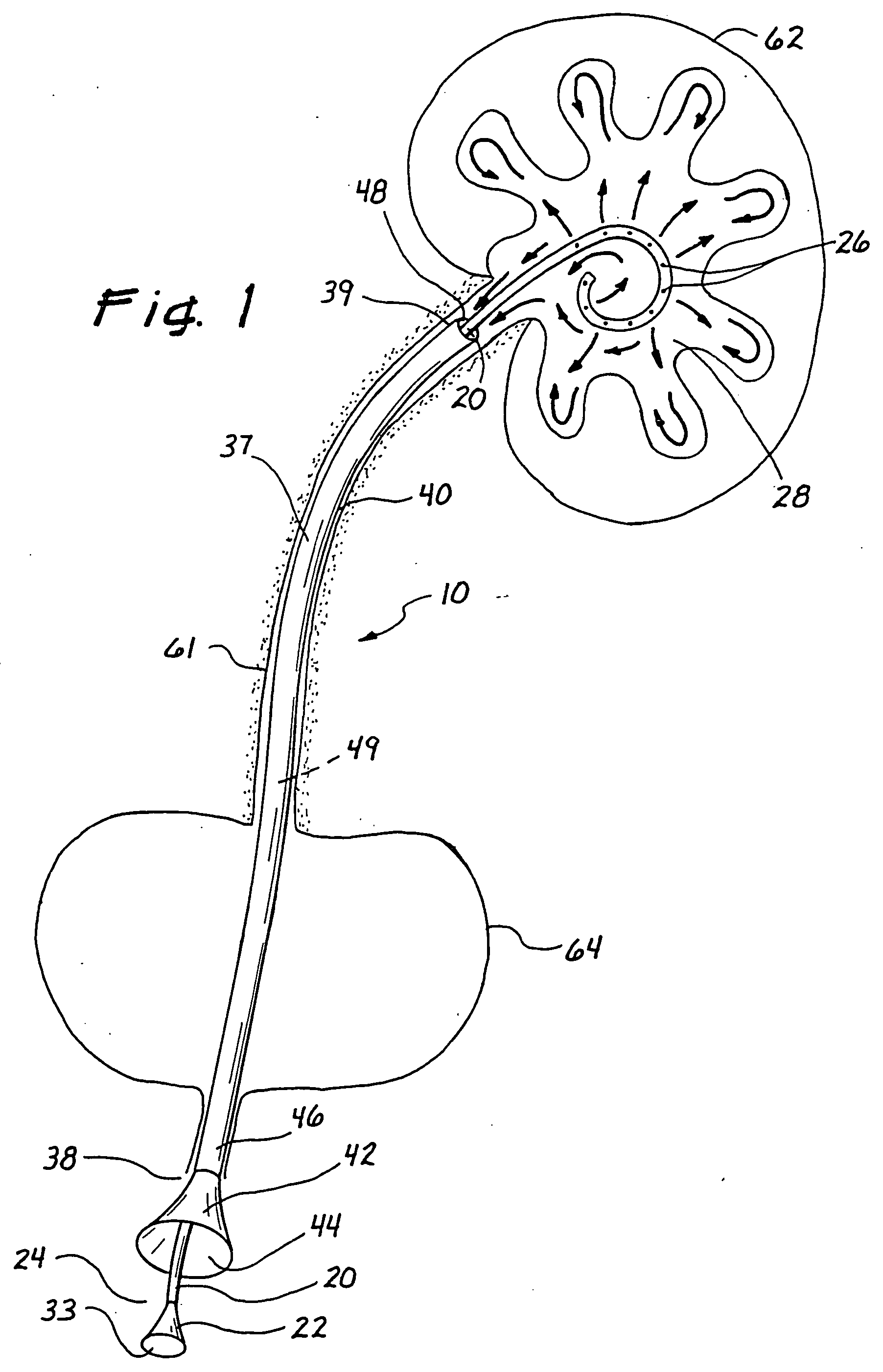
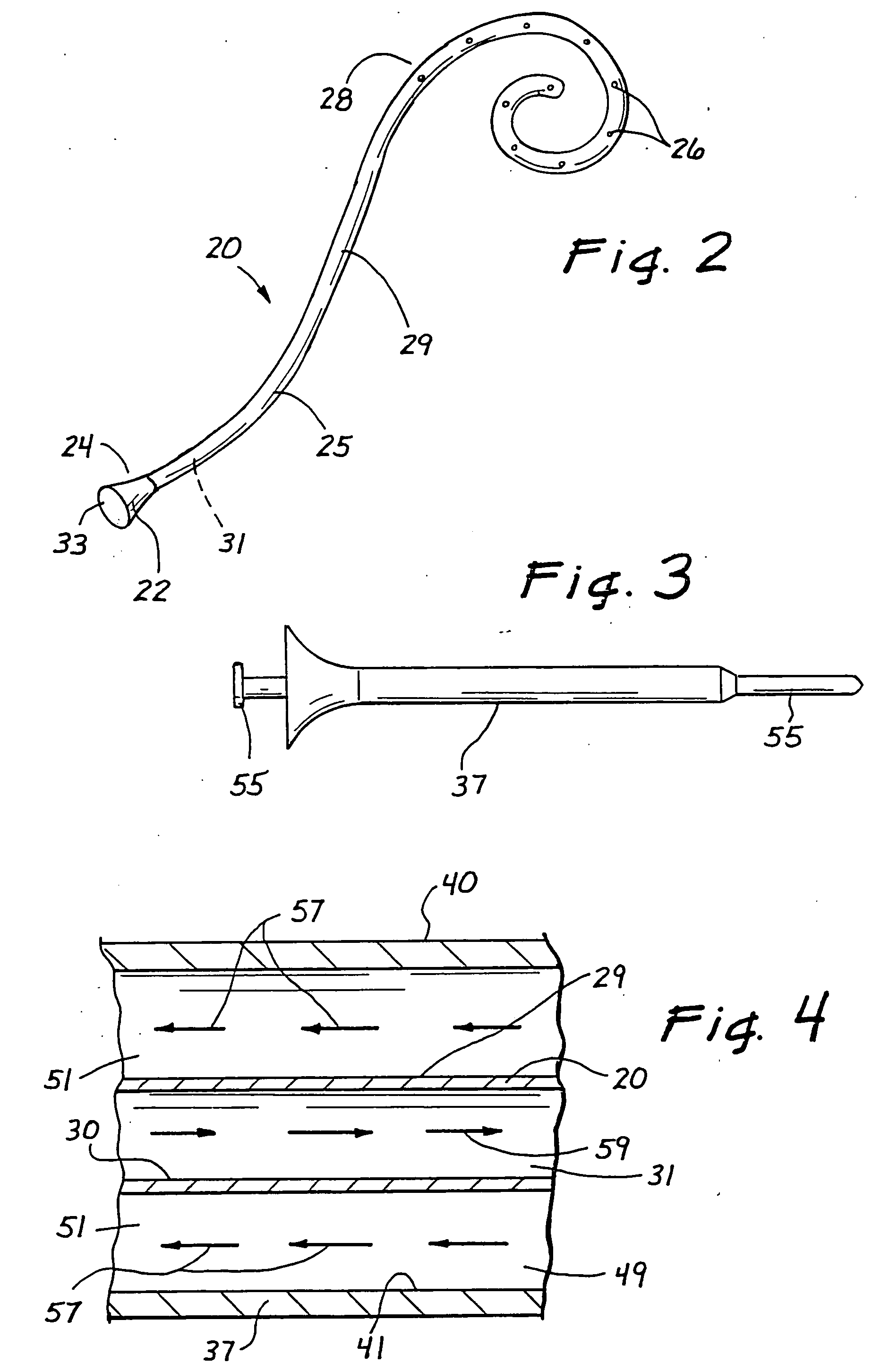
[0022]FIG. 1 illustrates a high-flow low-pressure irrigation system 10 in accordance with the invention. System 10 comprises an access sheath 37 and a flexible ureteral catheter 20 disposed inside sheath 37. Sheath 37 includes a sheath outer surface 40 and a sheath inner surface 41 as best illustrated in FIG. 4. Referring back to FIG. 1, a sheath funnel 42 is disposed at a sheath proximal end 38 and includes a sheath proximal opening 44. A sheath tube 46 extends distally from sheath funnel 42 to a sheath distal end 39 where a sheath distal opening 48 is disposed. Sheath tube 46 defines a sheath lumen 49. It is preferable that the length of sheath 37 is less than the length of catheter 20 such that catheter 20 extends through sheath 37 and protrudes out of sheath distal opening 48. In particular, when extended through sheath 37, a distal tube portion 28 of catheter 20 is not enclosed within sheath 37. Referring to FIG. 2, catheter 20 is preferably curled resembling a pigtail at dista...

second embodiment

[0030]FIG. 6 illustrates a high-flow low-pressure irrigation system 10b in accordance with the invention. Irrigation system 10b comprises an access sheath 37b and a flexible ureteral catheter 20b disposed inside the access sheath 37b. Sheath 37b is unique in that in that it has a hub 66 at a sheath proximal end 38b. Hub 66 forms a seal with catheter 20b and includes an exit port or exit tube 68 for directing returning fluid 57 outward. In another embodiment of the invention, an irrigation system 10c may include a proximal Y-fitting hub 71 as illustrated in FIG. 7. Y-fitting hub 71 includes a first tube 73 adapted for receiving a flexible catheter 20c and a second tube 75 adapted for directing the returning fluid outward. Both tubes 73 and 75 are in fluid communication with each other and sheath lumen 49c. Tube 73 includes a proximal tube end 77 that forms a seal with flexible catheter 20c to prevent the returning fluid from spilling.

[0031] In a preferred embodiment of system 10c, th...


PUM


Abstract

A high-flow low-pressure irrigation system (10) for directing a fluid to and recovering the fluid from an area within a body, the irrigation system (10) comprising a sheath (37) and a flexible catheter (20) disposed in the sheath (37). The catheter (20) comprises a plurality of apertures (26) at a distal pigtail portion (28). The fluid is directed through the apertures (26) and recovered through the sheath (37). Renal applications include alkaline irrigation for dissolution or uric acid stones, chemo-dissolution of cystine stones, irrigation with chemotherapy drugs after ureteroscopic tumor management, antibiotic irrigation for severe infection (e.g. fungal and bacterial), and irrigation of thrombotic agents (Alum Or direct delivery of Amicar for renal bleeding).

Description

[0001] This application claims benefit to U.S. Provisional Application Ser. No. 60 / 329,139 filed Oct. 12, 2001.BACKGROUND OF THE INVENTION [0002] 1. Field of the Invention [0003] The present invention generally relates to renal cooling systems and, more particularly, to a high-flow low-pressure irrigation system for use in minimally invasive surgery. [0004] 2. Description of Related Art [0005] Complex renal surgery frequently requires transient interruption of the renal vasculature. Renal hypothermia is known in the field to protect the kidney from ischemia-induced nephron loss and to preserve renal function during partial nephrectomy, renovascular surgery and kidney transplantation. Renal hypothermia is achieved by clamping the renal artery and packing the kidney in ice or slush. Although this practice provides sufficient cooling of the kidney, it presents many drawbacks such as exposing the surrounding structures to the cooling effects of the ice or slush and obscuring the surgica...

Claims


Application Information

Patent Timeline
Patent Type & Authority Applications(United States)
IPC IPC(8): A61M3/00A61M1/00A61M25/00A61M31/00A61M37/00
CPCA61M25/0032A61M25/0041A61M25/0068A61M25/007A61M27/008A61M2210/1082A61M2025/0004A61M2025/0034A61M2025/0073A61M2025/0681A61M2205/3331A61M31/00
Inventor LANDMAN, JAIMECLAYMAN, RALPH V.EWERS, RICHARD C.
Owner APPL MEDICAL RESOURCES CORP
Why Eureka
Try Eureka