Robot device and control method of robot device

a robot and control method technology, applied in the field of robot devices, can solve the problems of inability to meet various requests for changing locomotion, inability to erect the robot, and long time and labor

Inactive Publication Date: 2005-05-19
SONY CORP
View PDF28 Cites 66 Cited by
  • Summary
  • Abstract
  • Description
  • Claims
  • Application Information

AI Technical Summary

Benefits of technology

[0023] An object of the present invention is to provide a superior robot apparatus that can properly generate motion patterns including a walking pattern in an actual apparatus thereof and in real time, and a control method for the robot apparatus.
[0024] Another object of the present invention is to provide a robot apparatus that can execute proper walking control while ensuring a consistent dynamic model for the generation of a walking pattern and various adaptive control operations, and a control method for the robot apparatus.
[0025] A further object of the present invention is to provide a superior robot apparatus that can properly control the stabilization of a robot body in an embedded CPU having limited calculation resources, and a control method for the robot apparatus.

Problems solved by technology

Most of the human working or living spaces are adapted to the bodily mechanism or behavioral pattern of human beings in the form of erect walking on two legs, and there are many obstacles therein for existing mechanical systems having wheels or other driving devices as transfer means.
This is because falling implies interruption of the operation being executed by the robot, and a lot of time and labor is taken for the robot to erect itself from its fallen state and to restart the operation.
This is also because the falling may inflict fatal damage not only to the robot itself, but also to the object colliding with the falling robot.
In such a case, since the reference walking pattern is given as fixed data, it is impossible to meet various requests to change the locomotion.
However, it is impossible to cover all possible walking patterns, which can be said to be innumerable.
In a case in which a motion different from a motion assumed when a reference walking pattern is generated is requested of a specific joint (e.g., an upper limb of a humanoid robot) during execution time, since the motion of the specific joint is treated as a disturbance, the burden on the stabilizing algorithm is increased.
For example, when the mass of the upper limbs is large, it is considered that it is difficult to meet a motion request, for example, to violently swing the upper limbs at a given timing during walking.
Furthermore, since a simple dynamic model is constructed corresponding to each adaptive control function, expandability for adding adaptive control functions is low, and the amount of calculation is increased.
In other words, there is no consistency between dynamic models used in the generated walking pattern and various stabilizing algorithms.
For this reason, unexpected interference occurs between different models.
It is impossible to deny the probability that such an interference will cause phenomena, such as oscillation and divergence, in the control system and will reduce the walking performance.
Various stabilizing algorithms, as well as the generated walking pattern, are not controlled by independent dynamics, but, in general, mutually interfere with one another.

Method used


Image

  • Robot device and control method of robot device
  • Robot device and control method of robot device
  • Robot device and control method of robot device

Examples


Embodiment Construction

[0055] An embodiment of the present invention will be described in detail below with reference to the drawings.

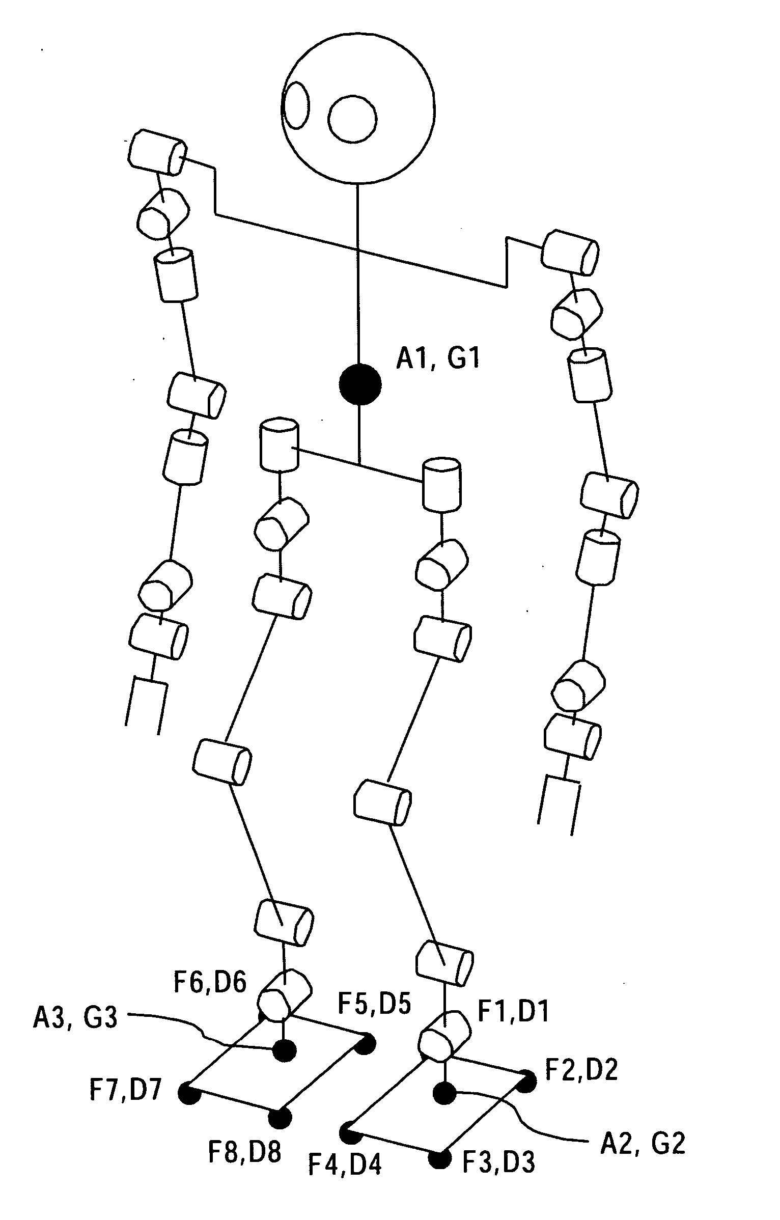
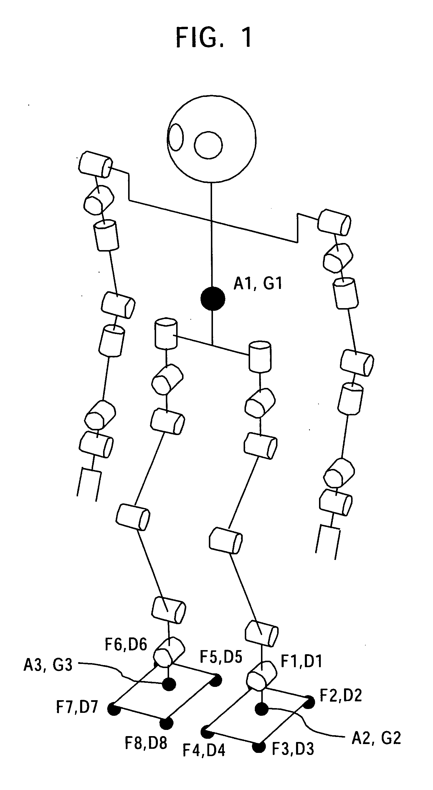
[0056]FIG. 1 schematically shows the degree-of-freedom system in a legged mobile robot that carries out the present invention.

[0057] A robot shown in the figure is a humanoid robot having two legs and two arms. The robot has a body with four limbs attached thereto, and includes right and left arms each having seven degrees of freedom of a shoulder joint pitching axis, a shoulder joint rolling axis, an upper-arm yawing axis, an elbow joint pitching axis, a forearm yawing axis, a wrist rolling axis, and a wrist pitching axis, and right and left legs each having six degrees of freedom of a hip joint yawing axis, a hip joint rolling axis, a hip joint pitching axis, a knee pitching axis, an ankle pitching axis, and an ankle rolling axis.

[0058] The degrees of freedom of the joints are, in reality, realized by actuator motors. In this embodiment, small AC servo actuators in whi...


PUM


Abstract

A locomotion control system is constructed to input the quantity of materials in the real world, such as the quantity of motion state of a robot, external force and external moment, and environmental shapes, measured with sensors or the like. By integrating all calculations for maintaining a balance of the body into a single walking-pattern calculating operation, both a locomotion generating function and an adaptive control function are effectively served, the consistency of dynamic models is ensured, and interference between the dynamic models is eliminated. Calculations for generating a walking pattern of the robot can be performed in an actual apparatus and in real time in a manner in which parameters, such as a boundary condition concerning the quantity of motion state, external force and external moment, and the trajectory of the sole, are settable.

Description

TECHNICAL FIELD [0001] The present invention relates to a robot apparatus having at least a plurality of movable legs, and a control method for the robot apparatus, and particularly, to a robot apparatus that executes locomotion generation and adaptive control by using a predetermined dynamic model, and a control method for the robot apparatus. [0002] More particularly, the present invention relates to a robot apparatus that generates a motion pattern, including a walking pattern, in an actual apparatus in real time, and a control method for the robot apparatus, and even more particularly, to a robot apparatus that properly controls the walking while ensuring the consistency between dynamic models for walking-pattern generation and various adaptive control operations, and a control method for the robot apparatus. BACKGROUND ART [0003] A mechanical apparatus, which makes motions similar to human motions by using an electrical or magnetic effect, is called a “robot”. It is said that t...

Claims


Application Information

Patent Timeline
Patent Type & Authority Applications(United States)
IPC IPC(8): B62D57/02B62D57/032
CPCB62D57/032B62D57/02
Inventor NAGASAKA, KENICHIRO
Owner SONY CORP
Why Eureka
Try Eureka