Vibration-suppressing cutting tool
a cutting tool and vibration-suppression technology, applied in the direction of manufacturing tools, band saws, saw chains, etc., can solve the problems of increasing the machining cost of producing an inside diameter-cutting holder, the size of the holder is limited, and the structure tends to generate chatter vibrations, etc., to achieve the effect of suppressing chatter vibrations, simple structure and adapting to a wide range of cutting diameter and cutting condition
- Summary
- Abstract
- Description
- Claims
- Application Information
AI Technical Summary
Benefits of technology
Problems solved by technology
Method used
Image
Examples
example 1
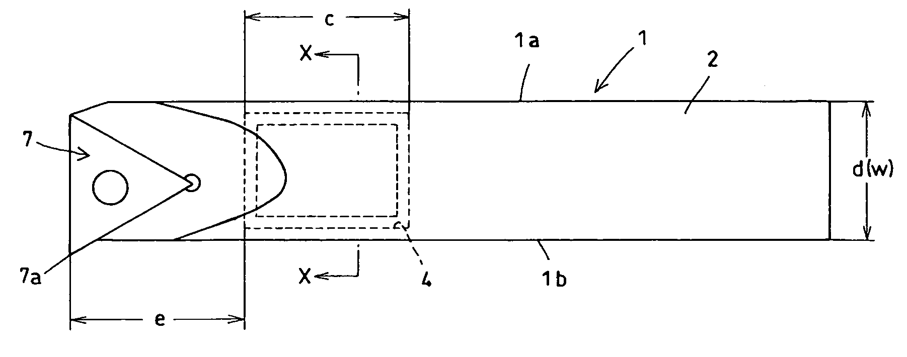
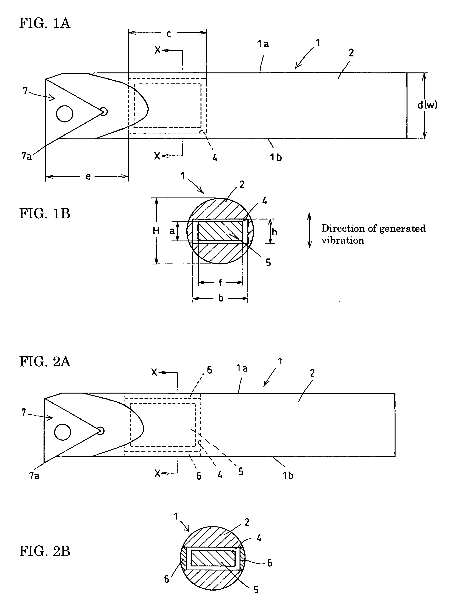
[0061]FIGS. 6A and 6B show an embodiment of the vibration-suppressing cutting tool of the present invention. The tool shown is a boring bar having the following structure. An indexable insert 7 is clamped to the tip portion of a holder 1 with a clamping means 8 so that it can be easily attached and detached. A shank portion 2 of the holder 1 is provided with a hole passing through the shank from one side to the other. The hole is machined by a method such as electrical-discharge machining at a position relatively close to the tip of the holder 1. The hole acts as a pocket 4. A weight 5 made of cemented carbide having a specific gravity of 15.1 is inserted into the pocket 4. Both openings of the pocket 4 are closed with caps 6 so that the weight 5 is unable to rush out to the outside.
[0062] The weight 5 housed in the pocket 4 has a size (height a and width f) smaller than the size of the pocket by 0.15 mm or so. In other words, the weight 5 is allowed to move within the range of the...
example 2
[0067]FIGS. 9A to 9C show an embodiment that is effective in the case where the machining precision is considered particularly important. The tool shown in FIGS. 6A and 6B can have a large weight, so that it can easily enhance the effect of suppressing the chatter vibration. However, because it has a pocket 4 passing through the shank portion 2, the stiffness of the holder tends to decrease, decreasing the machining precision. The vibration-suppressing cutting tool shown in FIGS. 9A to 9C can solve the problem.
[0068] In the tool shown in FIGS. 9A to 9C, a shank portion 2 is provided with a pocket 4 having the shape of a nearly rectangular solid. The pocket 4 is machined with an end mill from a side 1a of a holder 1 opposite to the side at which a cutting corner 7a is placed. To facilitate the machining with an end mill, both ends of the pocket 4 have the shape of an arc. To suppress the decrease in the stiffness of the holder 1, the pocket 4 forms a blind hole, which leaves a resid...
example 3
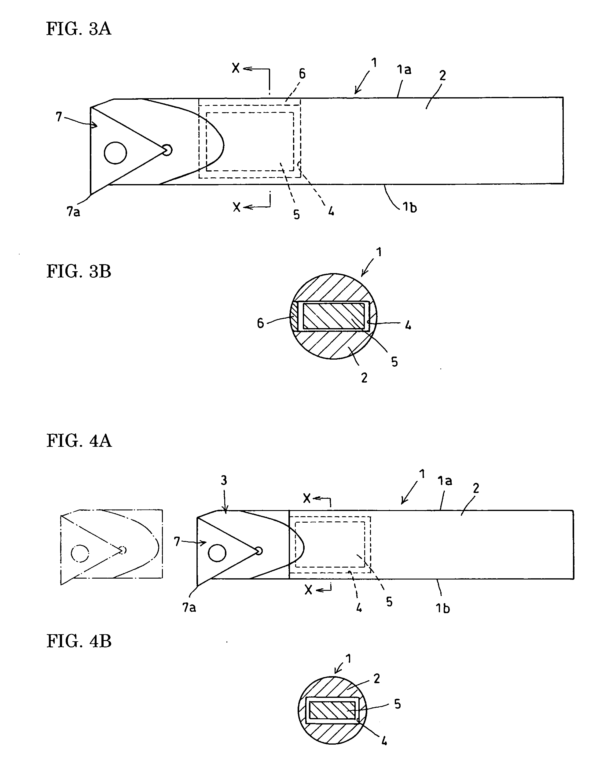
[0087]FIGS. 14A and 14B show yet another embodiment. In the vibration-suppressing cutting tool shown in FIGS. 14A and 14B, a shank portion 2 and a head portion 3 of a holder 1 are first separately formed and then combined with each other to form an integrated body. The head portion 3 may either be bonded to the shank portion 2 unseparably or be attached to it separably so that the head portion 3 can be replaced when it is broken.
[0088] This structure allows the formation of a pocket 4 having an opening at the tip of the shank portion 2 so that a weight 5 can be inserted into it. In this case, the head portion 3 acts as a cap, eliminating the need to provide a specific cap. When the shank portion 2 is formed with cemented carbide and a pocket 4 is formed through such a method as electrical-discharge machining, an inside diameter-cutting vibration-suppressing cutting tool can be obtained that has high stiffness and an extremely high effect in suppressing the chatter vibration.
PUM
| Property | Measurement | Unit |
|---|---|---|
| specific gravity | aaaaa | aaaaa |
| specific gravity | aaaaa | aaaaa |
| specific gravity | aaaaa | aaaaa |
Abstract
Description
Claims
Application Information
 - R&D
- Intellectual Property
- Life Sciences
- Materials
- Tech Scout
- Unparalleled Data Quality
- Higher Quality Content
- 60% Fewer Hallucinations
Browse by: Latest US Patents, China's latest patents, Technical Efficacy Thesaurus, Application Domain, Technology Topic, Popular Technical Reports.
© 2025 PatSnap. All rights reserved.Legal|Privacy policy|Modern Slavery Act Transparency Statement|Sitemap|About US| Contact US: help@patsnap.com


