Vibration-suppressing cutting tool

a cutting tool and vibration-suppression technology, applied in the direction of manufacturing tools, band saws, saw chains, etc., can solve the problems of increasing the machining cost of producing an inside diameter-cutting holder, the size of the holder is limited, and the structure tends to generate chatter vibrations, etc., to achieve the effect of suppressing chatter vibrations, simple structure and adapting to a wide range of cutting diameter and cutting condition

Active Publication Date: 2009-02-17
SUMITOMO ELECTRIC HARDMETAL CORP
View PDF46 Cites 6 Cited by
  • Summary
  • Abstract
  • Description
  • Claims
  • Application Information

AI Technical Summary

Benefits of technology

[0008]An object of the present invention is to offer a vibration-suppressing cutting tool that can solve the above-described problems posed by conventional vibration-suppressing cutting tools and that is provided with a holder which is low-cost, which has an extremely high effect in suppressing chatter vibrations, which has a simple structure, and which is capable of adapting to a wide range of cutting diameter and cutting condition.

Problems solved by technology

In particular, in a boring bar for cutting an inside diameter, the size of the holder is limited by the hole diameter of a workpiece.
This structure tends to generate chatter vibrations.
This structure increases the machining cost for producing an inside diameter-cutting holder, in particular, which has a long, small-diameter shank, because the hole must be drilled by using a gun drill or the like.
This structure decreases the stiffness of the holder.
In addition, the complicated structure poses a problem of increasing the cost.
In addition, the complicated structure of these holders also poses the following problems: (a) the diameter of the shank of the holder is limited, and therefore the cutting diameter of the inside-diameter cutting is limited, and (b) the cutting condition to achieve the vibration-suppressing effect is limited.

Method used


Image

  • Vibration-suppressing cutting tool
  • Vibration-suppressing cutting tool
  • Vibration-suppressing cutting tool

Examples


example 1

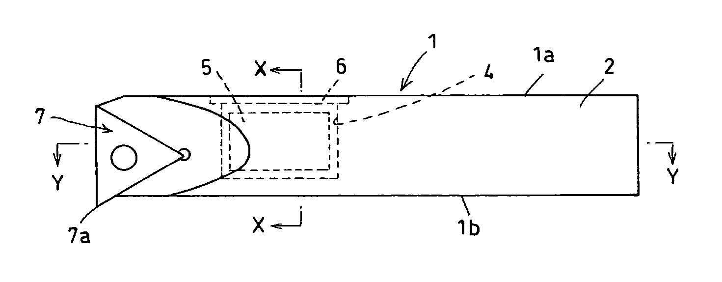
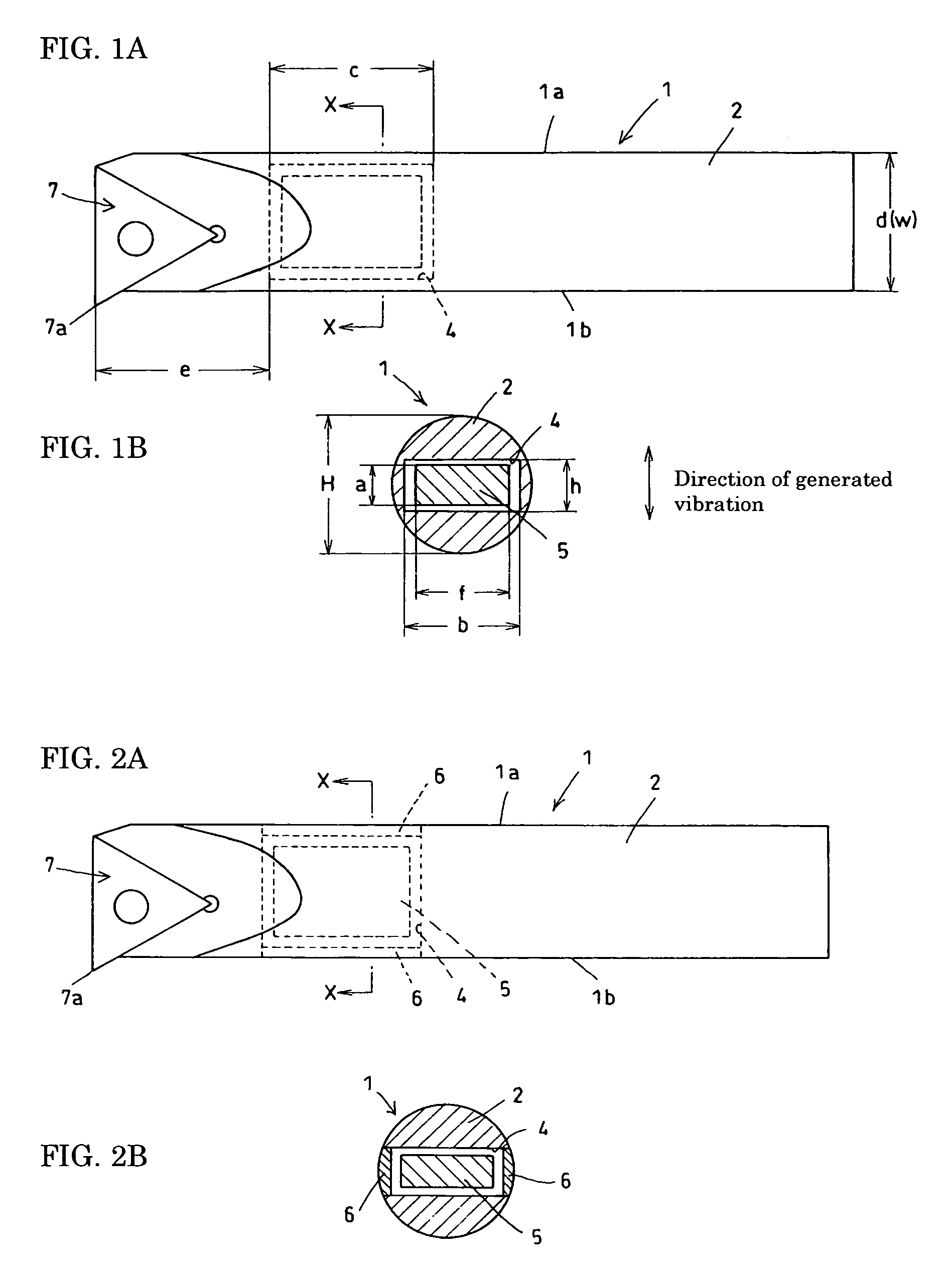
[0061]FIGS. 6A and 6B show an embodiment of the vibration-suppressing cutting tool of the present invention. The tool shown is a boring bar having the following structure. An indexable insert 7 is clamped to the tip portion of a holder 1 with a clamping means 8 so that it can be easily attached and detached. A shank portion 2 of the holder 1 is provided with a hole passing through the shank from one side to the other. The hole is machined by a method such as electrical-discharge machining at a position relatively close to the tip of the holder 1. The hole acts as a pocket 4. A weight 5 made of cemented carbide having a specific gravity of 15.1 is inserted into the pocket 4. Both openings of the pocket 4 are closed with caps 6 so that the weight 5 is unable to rush out to the outside.

[0062]The weight 5 housed in the pocket 4 has a size (height a and width f) smaller than the size of the pocket by 0.15 mm or so. In other words, the weight 5 is allowed to move within the range of the c...

example 2

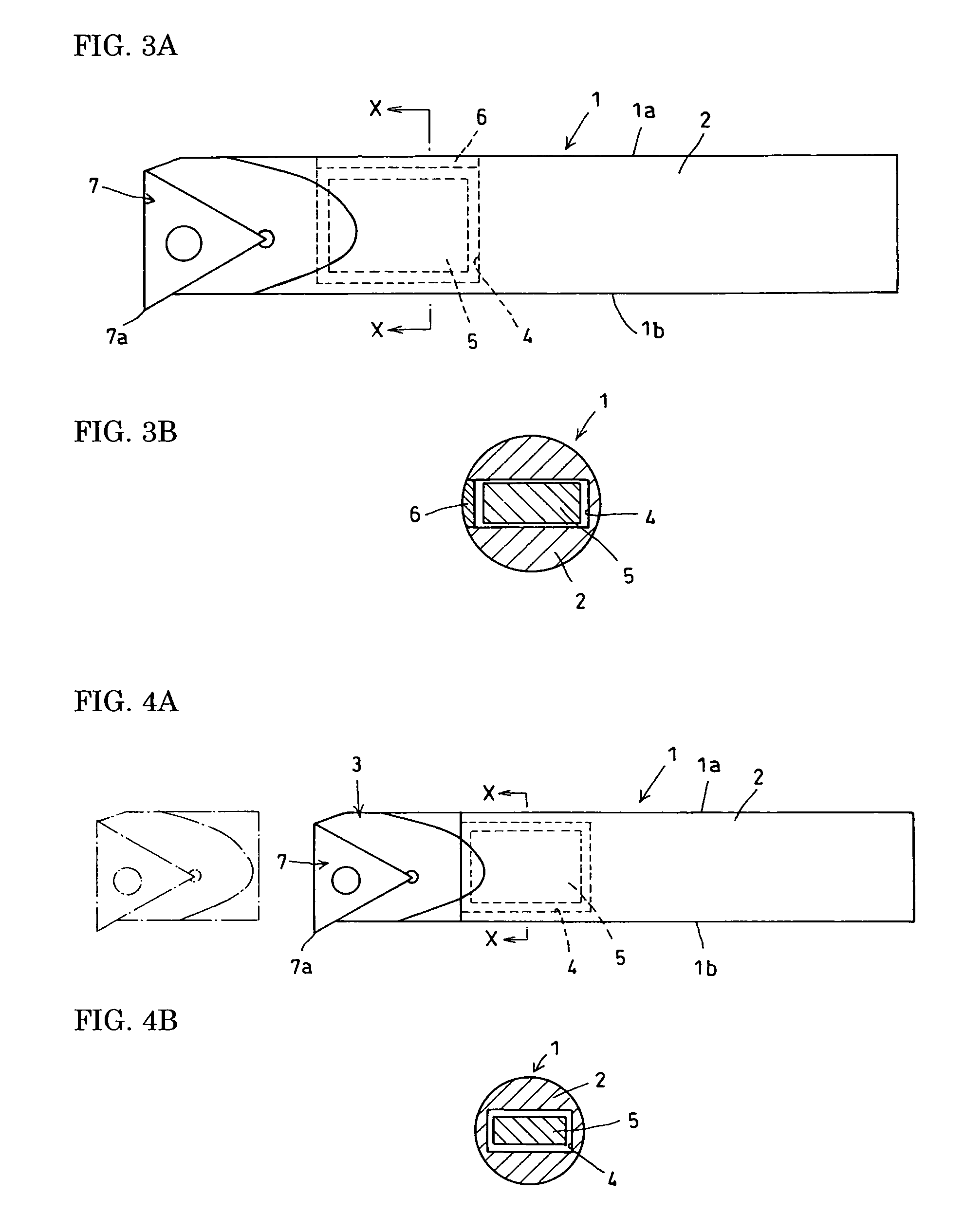
[0067]FIGS. 9A to 9C show an embodiment that is effective in the case where the machining precision is considered particularly important. The tool shown in FIGS. 6A and 6B can have a large weight, so that it can easily enhance the effect of suppressing the chatter vibration. However, because it has a pocket 4 passing through the shank portion 2, the stiffness of the holder tends to decrease, decreasing the machining precision. The vibration-suppressing cutting tool shown in FIGS. 9A to 9C can solve the problem.

[0068]In the tool shown in FIGS. 9A to 9C, a shank portion 2 is provided with a pocket 4 having the shape of a nearly rectangular solid. The pocket 4 is machined with an end mill from a side 1a of a holder 1 opposite to the side at which a cutting corner 7a is placed. To facilitate the machining with an end mill, both ends of the pocket 4 have the shape of an arc. To suppress the decrease in the stiffness of the holder 1, the pocket 4 forms a blind hole, which leaves a residua...

example 3

[0087]FIGS. 14A and 14B show yet another embodiment. In the vibration-suppressing cutting tool shown in FIGS. 14A and 14B, a shank portion 2 and a head portion 3 of a holder 1 are first separately formed and then combined with each other to form an integrated body. The head portion 3 may either be bonded to the shank portion 2 unseparably or be attached to it separably so that the head portion 3 can be replaced when it is broken.

[0088]This structure allows the formation of a pocket 4 having an opening at the tip of the shank portion 2 so that a weight 5 can be inserted into it. In this case, the head portion 3 acts as a cap, eliminating the need to provide a specific cap. When the shank portion 2 is formed with cemented carbide and a pocket 4 is formed through such a method as electrical-discharge machining, an inside diameter-cutting vibration-suppressing cutting tool can be obtained that has high stiffness and an extremely high effect in suppressing the chatter vibration.


PUM

PropertyMeasurementUnit
specific gravityaaaaaaaaaa

Abstract

A holder 1 has a shank portion 2 provided with a pocket 4 having the shape of a nearly rectangular solid. The pocket 4 is placed at a position relatively close to the tip of the tool. In the cross section of the shank, the pocket 4 has a width of 50% to 100% of the shank diameter or width, a height of 20% to 50% of the shank height, and a length of 50% to 250% of the shank diameter or height. A weight 5 is inserted into the pocket 4 such that the weight is movable but unable to rush out. The weight 5 has the shape of a nearly rectangular solid and is made of a material having a specific gravity comparable to or greater than that of the material of the shank portion.

Description

BACKGROUND OF THE INVENTION[0001]1. Field of the Invention[0002]The present invention relates to a low-cost vibration-suppressing cutting tool that can significantly reduce chatter vibrations mainly in cutting operations in which chatter vibrations cause problems.[0003]2. Description of the Background Art[0004]It has been well known that chatter vibrations can be suppressed by a method that uses inertia by incorporating a damper or similar member into a holder. In particular, in a boring bar for cutting an inside diameter, the size of the holder is limited by the hole diameter of a workpiece. Consequently, the amount of over-hang must be increased by using a slender shank. This structure tends to generate chatter vibrations. As a result, the prior art on the vibration-suppressing cutting tool mainly relates to a boring bar. Therefore, the following explanation is made by mainly referring to the boring bar as an example.[0005]For example, the published Japanese patent application Tok...

Claims


Application Information

Patent Timeline
Patent Type & Authority Patents(United States)
IPC IPC(8): B27B33/12B23B27/00B23B29/00B23B29/02B23B29/03B23B29/04
CPCB23B27/002B23B29/022Y10T82/2585Y10T83/9319Y10T83/929B23B29/00B23B29/02B23B29/03B23B29/04
Inventor MURAKAMI, DAISUKEKIMURA, NORIHIDEOKIDA, JUNYA
Owner SUMITOMO ELECTRIC HARDMETAL CORP
Why Eureka
Try Eureka