Heating cooking device

a cooking device and heat sink technology, applied in the field of cooking ovens, can solve the problems of uneven cooking of foods, difficult to transmit a sufficient amount of heat to the bottom face of foods, and inability to heat foods evenly, etc., to achieve the effect of reducing the cost of the heater, reducing the shape of the heater, and alleviating uneven heating of foods

Inactive Publication Date: 2005-05-26
SHARP KK
View PDF5 Cites 18 Cited by
  • Summary
  • Abstract
  • Description
  • Claims
  • Application Information

AI Technical Summary

Benefits of technology

[0034] According to the present invention, the cooking oven constructed as described above is constructed as follows. The heater is a sheath heater, and the portion of the heater that generates a smaller amount of heat is a non-heat-generating portion of the sheath heater. With this construction, the portion of the heater that generates a smaller amount of heat can be formed with the non-heat-generating portion of the sheath heater. This helps simplify the shape of the heater, and thus helps reduce the cost required for the heater.
[0035] According to the present invention, the cooking oven constructed as described above is constructed as follows. At least part of the heater for heating the air that blows out from the upper blowout port is arranged on the upstream side of the region where the upper blowout port is arranged. With this construction, it is possible to make uniform the temperature of the hot air stream that blows out from different parts of the upper blowout port. This helps alleviate uneven heating of the foods.
[0036] According to the present invention, a cooking oven is constructed as follows. The cooking oven has a blowout port and a suction port for passage of a hot air stream formed inside a cooking chamber so as to be capable of forming a circulating air stream of the hot air stream and is capable of discharging a microwave into the cooking chamber so that foods are cooked with heat by the effect of the hot air stream or the microwave alone or by the combined effect of the hot air stream and the microwave. In this cooking oven, an upper blowout port is formed in the ceiling wall of the cooking chamber, a side blowout port for blowing out the hot air stream is formed in one of the inner side walls forming the four sides of the cooking chamber, and a suction port for sucking in the hot air stream is formed in one of the inner side walls other than the side inner wall in which the side blowout port is formed. The upper blowout port is so arranged that the air stream that blows out therefrom does not deflect downward the air stream that flows from the side blowout port to the foods. A wave feed port for discharging the microwave into the cooking chamber is formed in one of the inner side walls other than the inner side wall in which the side blowout port is formed. The wave feed port for discharging the microwave into the cooking chamber is so arranged as not to directly face the side blowout port. With this construction, the hot air stream from the upper blowout port does not deflect downward the hot air stream from the side blowout port, and thus the hot air stream from the side blowout port flows along the designed route and reaches the foods, transmitting a required amount of heat to a required portion of the foods. Thus, the hot air stream from the side blowout port can play its expected role satisfactorily, contributing to enhanced quality of the cooked target. Moreover, it is possible to prevent pollutants, such as oil dripping from the foods and food fragments, from settling on the wave feed port for the microwave by being carried by the hot air stream blowing out from the side blowout port. This helps avoid accumulation of such sprinkled pollutants, which may start fire or invite electrical discharge by the microwave.
[0037] According to the present invention, the cooking oven constructed as described above is constructed as follows. The wave feed port is arranged in the inner side wall in which the side blowout port is formed. With this construction, the hot air stream that blows out from the side blowout port does not hit the wave feed port, which is formed in the same wall surface as the side blowout port, and thus does not sprinkle the wave feed port with pollutants. This helps avoid accumulation of sprinkled pollutants, which may start fire or invite electrical discharge by the microwave.
[0038] According to the present invention, the cooking oven constructed as described above is constructed as follows. The wave feed port is arranged in one of the inner side walls other than the inner side wall in which the side blowout port is formed and in such a way that the lower end of the wave feed port is located above the height-direction center of the side blowout port. With this construction, the side blowout port and the wave feed port are deviated from each other in the vertical direction so as not to directly face each other. Thus, the hot air stream that blows out from the side blowout port is less likely to sprinkle the wave feed port with pollutants. This helps avoid accumulation of sprinkled pollutants, which may start fire or invite electrical discharge by the microwave.
[0039] According to the present invention, the cooking oven constructed as described above is constructed as follows. The wave feed port is arranged in the inner side wall facing the inner side wall in which the side blowout port is formed and in such a way that the wave feed port does not directly face half or more of the horizontal width of the side blowout port. With this construction, the side blowout port and the wave feed port are deviated from each other in the horizontal direction so as not to directly face each other. Thus, the hot air stream that blows out from the side blowout port is less likely to sprinkle the wave feed port with pollutants. This helps avoid accumulation of sprinkled pollutants, which may start fire or invite electrical discharge by the microwave. According to the present invention, a cooking oven is constructed as follows. The cooking oven has a blowout port and a suction port for passage of a hot air stream formed inside a cooking chamber to form a circulation of hot air stream so that foods are cooked with heat by the circulating air stream. In this cooking oven, an upper blowout port formed by a plurality of perforations is formed in the ceiling wall of the cooking chamber, and a side blowout port formed by a plurality of perforations is formed in one of the inner side walls forming the four sides of the cooking chamber. The perforations forming the upper blowout port are each provided with a cylindrical portion that is so formed as to project outward from the heating chamber so that those perforations of the upper blowout port are given an axial length equal to or greater than the thickness of the member forming the ceiling wall. On the other hand, the perforations forming the side blowout port are each so formed as to have an axial length equal to or smaller than the thickness of the member forming the inner side wall. With this construction, the upper blowout port functions as a nozzle. Thus, the hot air stream that blows out from the upper blowout port forms a stream in the shape of a beam and collides with the foods without diminishing its flow speed. This helps apply powerful hot-air impingement on the foods. On the other hand, the hot air stream that blows out from the side blowout port starts to spread as soon as it exits from the side blowout port. This hot air stream, when it hits the foods, encloses widely and softly the side and lower faces of the foods while applying thereto weakened impingement. This makes it possible to more effectively exploit the characteristics of different cooking methods, as both in cooking employing a hot-air-impingement method whereby a high-speed hot air stream is blown down from above and in preparation of sponge cake in which a higher weight is given to a hot air stream that blows out from the side blowout port. Moreover, since the axial-direction length of the perforations is secured by the cylindrical portion that projects outward from the heating chamber, while the upper blowout port is given a necessary axial length, the lower surface of the ceiling wall is given a flat shape without any projection. This makes cleaning of the cooking chamber easy, and also helps prevent the user's fingers from being injured by being caught by such projections.

Problems solved by technology

However, blowing out hot air streams simultaneously in vertical and horizontal directions causes the following problem.
This makes it hard to transmit a sufficient amount of heat to the bottom face of the foods 60.
This results in uneven cooking of the foods 60 from one part of it to another.
As such pollutants accumulate on the surface of the cover, they may start fire or invite electrical discharge by the microwave.

Method used


Image

  • Heating cooking device
  • Heating cooking device
  • Heating cooking device

Examples


first embodiment

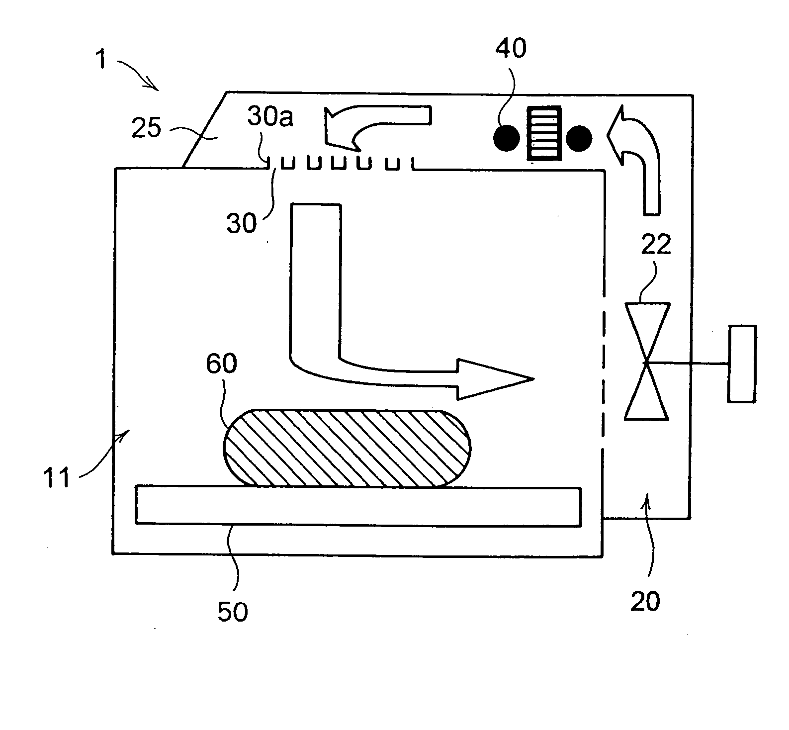
[0062] In the cooking oven 1 of the first embodiment, the arrangement is such that the air stream that blows out from the upper blowout port 30 does not deflect downward the air stream that blows from the side blowout port 31 to the foods 60. It should be understood that the expression “not deflect” used here does not solely mean “no deflection at all” but encompasses “a small degree of deflection.”

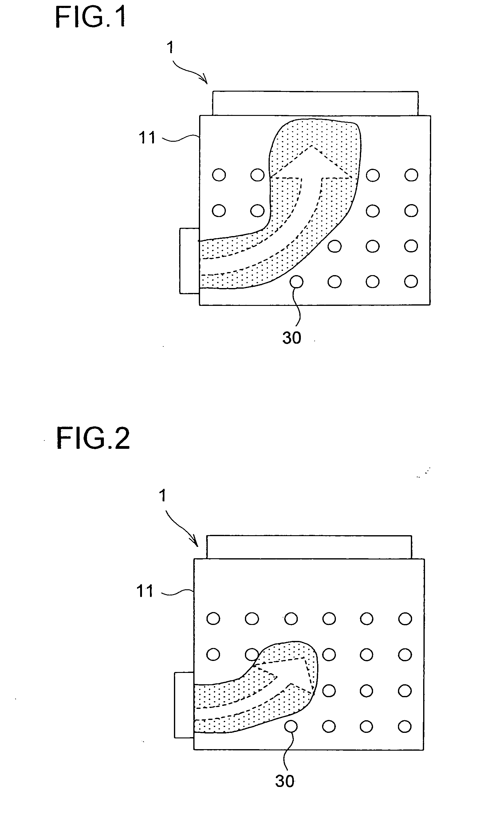
[0063] To prevent the air stream that blows from the side blowout port 31 to the foods 60 from being deflected downward, the following construction is adopted. The openness (the proportion of the area of the open portion) of the upper blowout port 30 formed in the ceiling wall 12 is made smaller in the portion thereof from which the air stream blows out toward the air stream that blows from the side blowout port 31 to the foods 60 than in the other portion thereof.

[0064] The difference in the openness of the upper blowout port 30 is produced by varying the distribution of the perforation...

second embodiment

[0078] Specifically, as in the second embodiment, the distribution of the perforations of the upper blowout port 30 is made sparser (including “no perforations at all”) in the portion thereof from which the air stream blows out toward the air stream that flows from the side blowout port 31 to the foods 60. The upper heater 40 is realized with a linear heater such as a Nichrome wire or a sheath heater. This linear heater is so laid as to avoid where the distribution of the perforations is sparser.

[0079] In this construction, the upper heater 40 generates a smaller amount of heat where the openness of the upper blowout port 30 is smaller. This helps avoid unnecessarily heating the air present in areas where no air stream passes. On the other hand, the heat generated by the upper heater 40 concentrates where the openness of the upper blowout port 30 is greater. This ensures efficient heating of air.

[0080] Practical methods for varying the amount of heat generated by the upper heater 4...

third embodiment

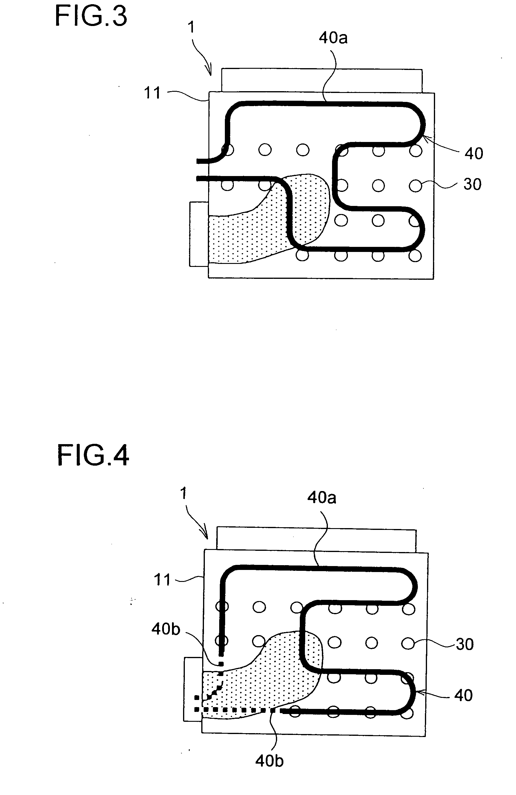
[0084] In the cooking oven 1 of the third embodiment, part 40a of the upper heater 40 is arranged on the upstream side, with respect to the stream of the hot air stream, of the region where the upper blowout port 30 is arranged. With this construction, the air heated by that part 40a of the upper heater 40 blows out from every perforation of the upper blowout port 30. This helps make uniform the temperature of the hot air that blows out from every perforation of the upper blowout port 30.

[0085]FIG. 4 shows a fourth embodiment of a cooking oven according to the invention. Also in the cooking oven 1 of the fourth embodiment, the upper heater 40 is so constructed as to generate a smaller amount of heat in the portion thereof located where the openness of the upper blowout port 30 is smaller than in the portion thereof located where the openness of the upper blowout port 30 is greater. This is achieved as follows. Here, as in the third embodiment, the openness of the upper blowout port ...


PUM


Abstract

A cooking oven, wherein an upper blowing port blowing hot air in vertical direction and a lateral blowing port for blowing hot air in horizontal direction are provided in a cooking chamber, the upper blowing port is provided in the ceiling wall of the cooking chamber, the lateral blowing port is provided in one of the right and left inside walls thereof, and a suction port is provided in the bottom inside wall thereof in the form of collected perforations, air in the cooking chamber sucked from the suction port is fed to an upper duct and a lateral duct, heated by an upper heater and a lateral heater, respectively, and blown from the upper blowing port and the lateral blowing port, and the distribution of the perforations of the upper blowing port is made such that the distribution of the perforations at a position where the air blows toward air current from the lateral blowing port to a cooked object is made coarser than that at the other positions so that the air current in horizontal direction cannot be obstructed.

Description

TECHNICAL FIELD [0001] The present invention relates to a cooking oven for cooking foods with heat by applying thereto a hot air stream or a hot air stream combined with a microwave. BACKGROUND ART [0002] Cooking ovens such as convection ovens and hot-air-impingement ovens that cook foods with heat by forming a circulated current of hot air stream inside a cooking chamber in which the foods are placed, are well known and widely used. Published documents such as, to name a few, Japanese Utility Model Published No. H6-23841 and Japanese Patent Applications Laid-Open Nos. H9-145063, H11-166737, 2000-329351, and 2001-311518 disclose examples of hot-air-circulation cooking ovens. On the other hand, Japanese Patent Published No. H9-503334 discloses an example of a hot-air-impingement cooking oven. Cooking ovens that combine a hot air stream with microwave heating are also well known (see Japanese Patent Applications Laid-Open Nos. H9-145063, H11-166737, and 2001-311518). [0003] Now, as th...

Claims


Application Information

Patent Timeline
Patent Type & Authority Applications(United States)
IPC IPC(8): F24C15/32F24C1/00
CPCF24C15/325
Inventor TATSUMU, NORIKIMIANDOH, YUZIARITA, TETSUICHIIWAMOTO, MASAYUKIUEDA, SHINYA
Owner SHARP KK
Why Eureka
Try Eureka