Quantum computing method and quantum computer

a quantum computer and computing method technology, applied in the field of quantum computing methods and quantum computers, can solve problems such as complex operation

Active Publication Date: 2005-05-26
KK TOSHIBA
View PDF3 Cites 53 Cited by
  • Summary
  • Abstract
  • Description
  • Claims
  • Application Information

AI Technical Summary

Benefits of technology

[0023]FIG. 4 is a schematic view showing light applied in executing a 1-qub

Problems solved by technology

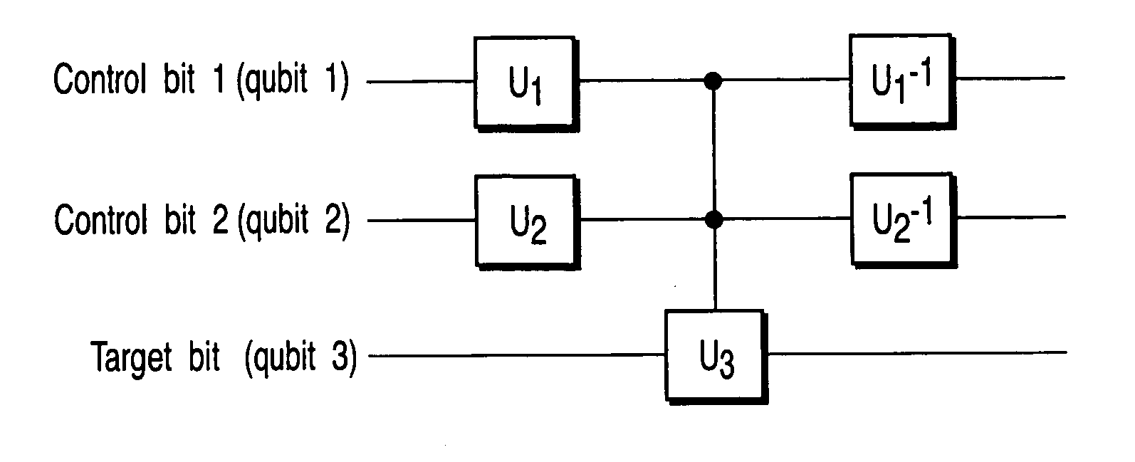
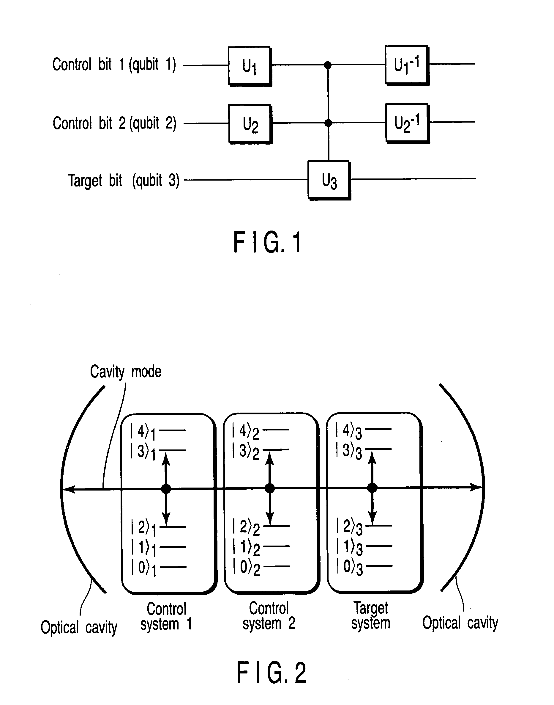
An attempt to realize a gate acting on three qubits or more (e.g., a quantum Toffoli gate, which is a 3-qubit gate and exchanges |0> and |1> of the one qubit only when the other two qubits are |1>|1>) by combining universal gates requires many gates and, therefore, the operation becomes complicated.
Since this method uses degenerate levels, when the user wants to operate the degenerate two states separately, the following problem ari

Method used


Image

  • Quantum computing method and quantum computer
  • Quantum computing method and quantum computer
  • Quantum computing method and quantum computer

Examples


embodiments

[0066] Embodiments of the present invention will be described hereinafter.

first embodiment

[0067]FIG. 5 is a schematic view showing the configuration of the quantum computer according to the first embodiment of the present invention. A Pr3+-doped Y2SiO5 crystal (Pr3+:Y2SiO5 crystal) is used as a sample 20. The hyperfine levels of Pr3+ are used for physical systems. FIG. 6 is a schematic view showing the hyperfine levels of Pr3+. Their hyperfine structure splitting is due to the nuclear spin of Pr3+ and a very long-coherence time can be realized at low temperature. It has been verified that coherent superposition states can be realized in this material using laser (K. Ichimura, K. Yamamoto, and N. Gemma, Phys. Rev. A 58, 4116, 1998). The hyperfine levels of Pr3+ are best suited to a quantum computing method of the present invention using three lower levels and two upper levels.

[0068] Since each level is degenerate in terms of the nuclear spin, if ions with suitable energy levels do not exist, the Zeeman levels adjusted by an external magnetic field can be used (see the se...

second embodiment

[0098] In this embodiment, the case in which a magnetic field is applied to the physical systems in order to set energy levels will be described. FIG. 9 is a schematic view showing the configuration of the quantum computer according to the second embodiment. In the apparatus of FIG. 9, coils 22 for applying a magnetic field to the sample 20 is provided in addition to the apparatus of FIG. 5 used in the first embodiment.

[0099] To verify that suitable energy levels can be set by applying a magnetic field to the sample 20, experiments were conducted in a frequency band separated from the frequency band used in the first embodiment by the free spectral range (FSR) of the cavity. In this case, three ions having desirable energy levels as shown in FIG. 7 did not exist. When examinations were made by changing the intensity of the applied magnetic field, three ions were found at a magnetic field of several hundreds of gauss which had energy levels of the transition frequency equal to the r...


PUM


Abstract

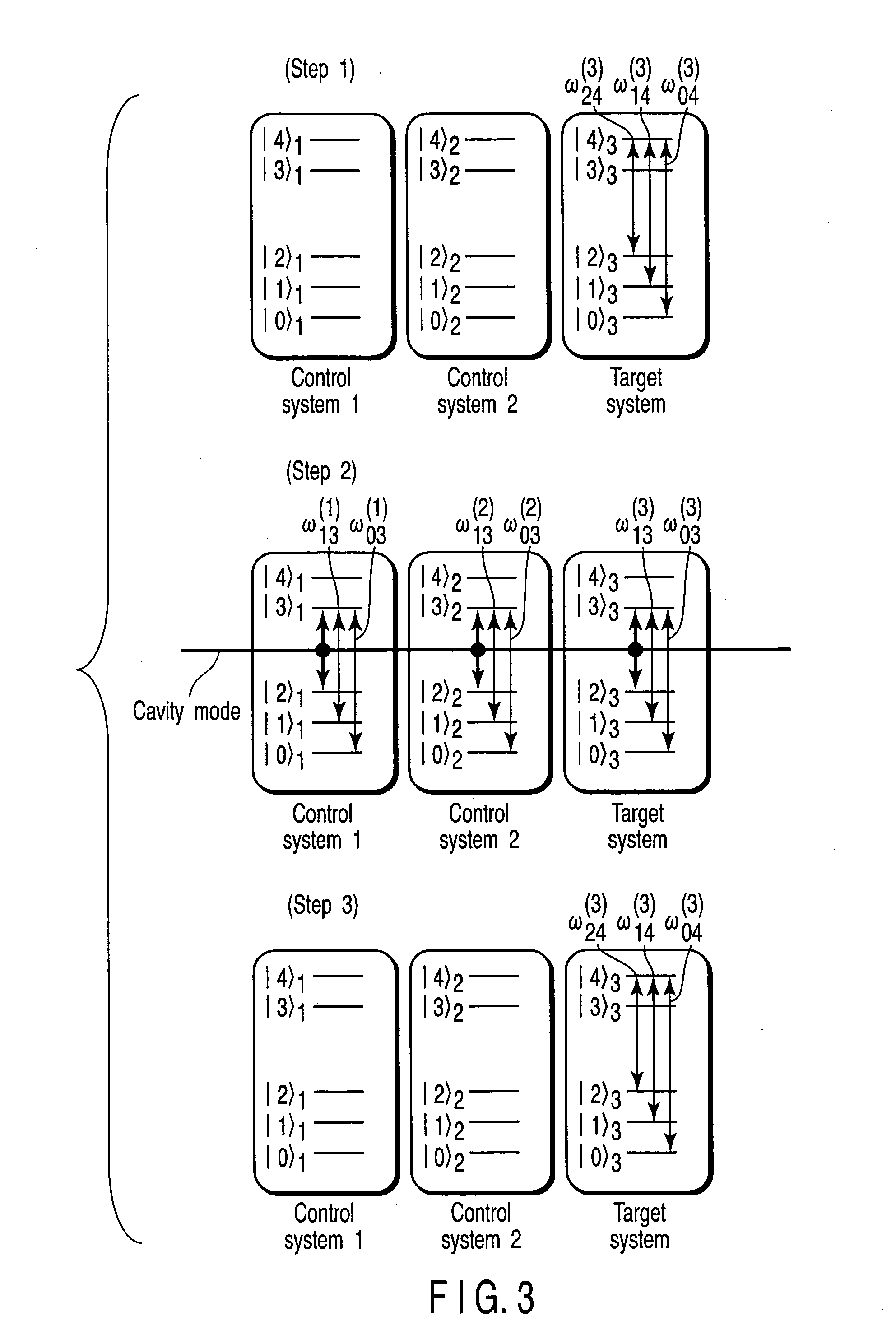
An (N+1) number of physical systems each having five energy levels |0>, |1>, |2>, |3>, and |4>, a qubit being expressed by |0> and |1>, are provided in an optical cavity having a cavity mode resonant with |2>-|3>, such that an N number of control systems and a target system are prepared. The target system is irradiated with light pulses resonant with |0>-|4>, |1>-|4>, and |2>-|4> to change a superposed state |c> to |2>. All of the physical systems are irradiated with light pulses resonant with |0>-|3> and |1>-|3>, and a phase of the light pulse resonant with the target system is shifted by a specific value dependent on a unitary transformation U. The target system is irradiated with light pulses resonant with |0>-|4>, |1>-|4>, and |2>-|4>, with a phase difference between them being set to a specific value dependent on the unitary transformation U, to return |2> to |c>.

Description

CROSS-REFERENCE TO RELATED APPLICATIONS [0001] This application is based upon and claims the benefit of priority from prior Japanese Patent Application No. 2003-372640, filed Oct. 31, 2003, the entire contents of which are incorporated herein by reference. BACKGROUND OF THE INVENTION [0002] 1. Field of the Invention [0003] This invention relates to a quantum computing method and a quantum computer using light. [0004] 2. Description of the Related Art [0005] In recent years, tremendous research effort has been directed toward quantum computers, which execute calculations on the basis of the principle of quantum mechanics. In quantum computers, two quantum states, |0> and |1>, form the basis of information. The two states correspond to bit 0 and bit 1, which form the basis of information in present-day computers. In quantum computers, however, the two quantum states are called quantum bits (qubits) to distinguish them from bits in present-day computers, since superposition state...

Claims


Application Information

Patent Timeline
IPC IPC(8): G02F3/00G06E3/00G06N99/00H01L31/0232H01S3/00H01S3/0947
CPCG06N99/002B82Y10/00G06N10/00
Inventor GOTO, HAYATOICHIMURA, KOUICHI
Owner KK TOSHIBA
Why Eureka
Try Eureka