Actuator for a vehicle door latch

a technology for actuating vehicles and door latches, which is applied in the direction of passenger lock actuation, electrical locking circuits, mechanical apparatus, etc., can solve the problems of increasing motor fatigue, reducing reliability, and methods of actuation, so as to reduce the power requirement of the motor, simplify the software, and minimize the complexity and the amount of wiring

Inactive Publication Date: 2005-05-26
INTEVA PRODUCTS LLC
View PDF4 Cites 21 Cited by
  • Summary
  • Abstract
  • Description
  • Claims
  • Application Information

AI Technical Summary

Benefits of technology

[0013] A further advantage of the invention is that a biasing member is not required since the motor returns the displacement member to the rest position. This reduces the power requirement of the motor since it does not have to overcome the resilience of the biasing member to actuate the displacement member.
[0014] Another advantage of the invention is that the motor is not required to stall. In the prior art, the motor needed to stall because the displacement member is driven onto a physical stop. Since the stepper motor of the present invention can achieve fixed rotation about a known datum, the positioning of the displacement member can be achieved without a physical stop.
[0015] A second aspect of the present invention provides a vehicle having two or more latches, and the stepper motors are controlled by a common control.
[0016] A third aspect of the present invention provides a system having a first latch, a second latch, and a controller to control the electric actuation of stepper motors of the first latch and the second latch. With the output of the first latch in a first output position, the output of the second latch in a second output position, and the displacement members of the first latch and the second latch in their respective intermediate rest positions, powered operation of the controller powers the stepper motors of the first latch and the second

Problems solved by technology

However, both of these methods of actuation have distinct disadvantages.
In both methods, the DC motor is repeatedly driven to stall, increasing motor fatigue and reducing reliabili

Method used


Image

  • Actuator for a vehicle door latch
  • Actuator for a vehicle door latch
  • Actuator for a vehicle door latch

Examples


Embodiment Construction

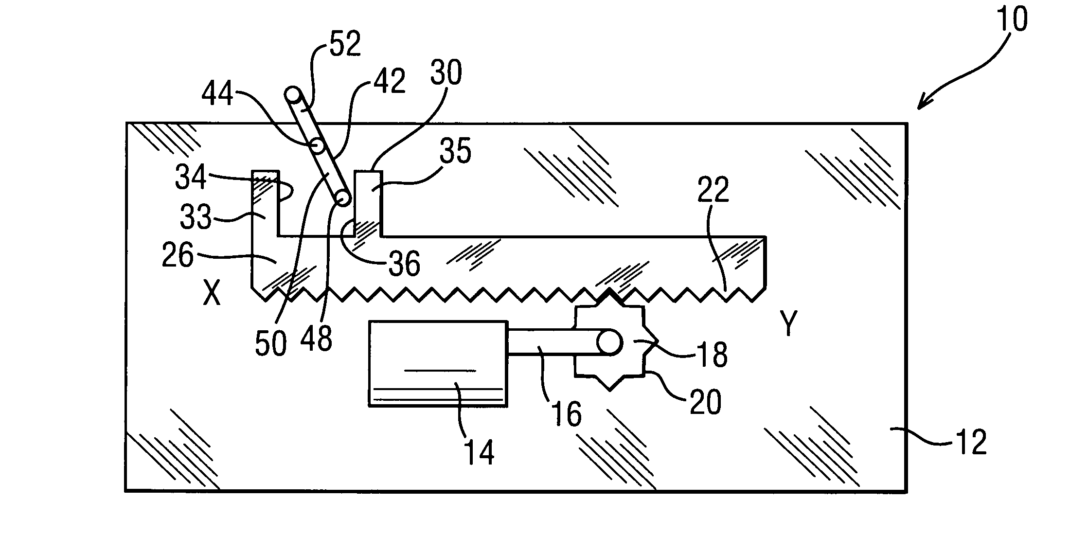
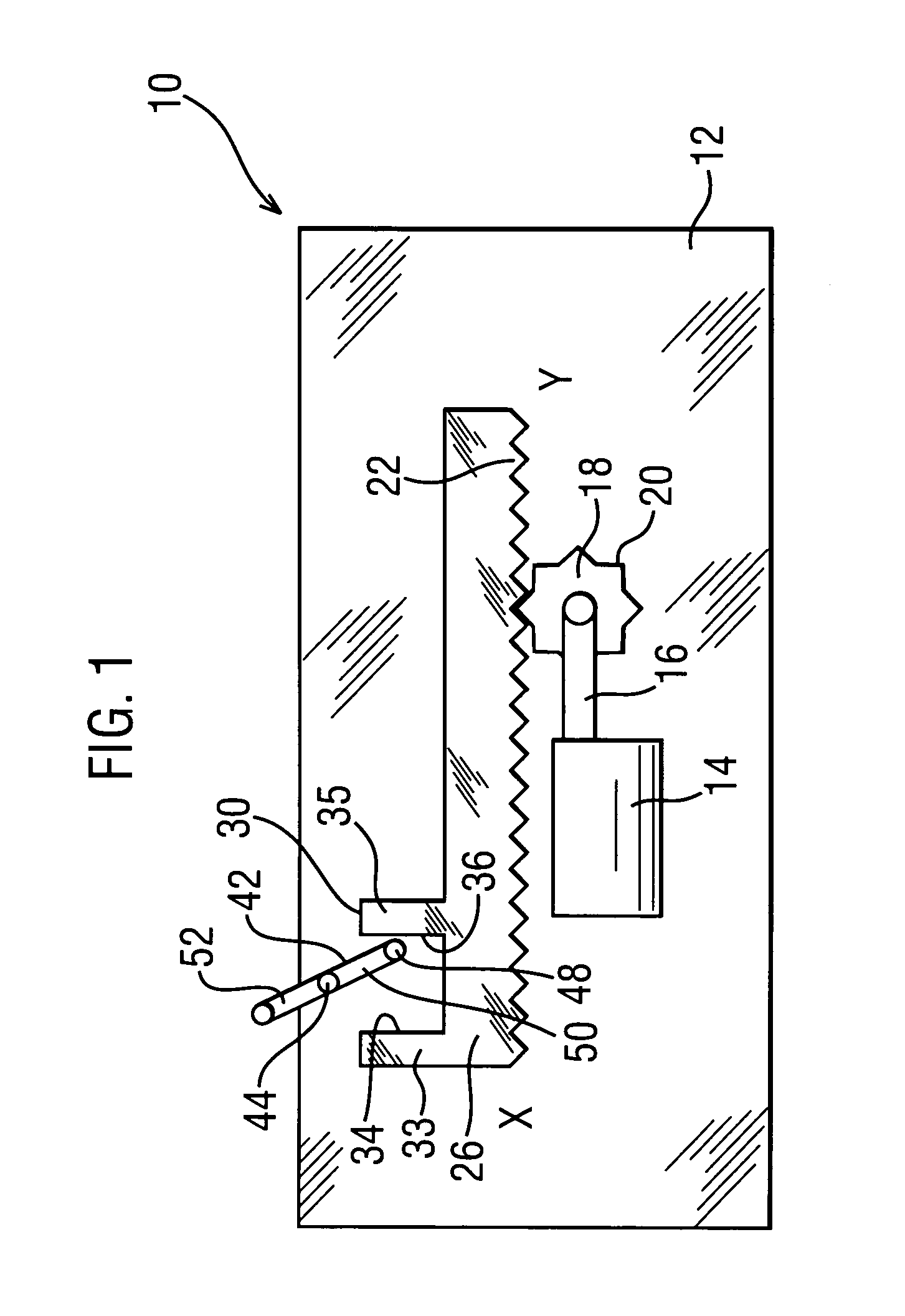
[0053]FIG. 1 illustrates an actuator 10 having a stepper motor 14 fixed to an actuator body 12. A pinion 18 having pinion teeth 20 is mounted on and driven by a stepper motor shaft 16 of the stepper motor 14. The pinion 18 engages with a displacement member 26 by a rack 22 disposed on a surface of the displacement member 26.

[0054] The displacement member 26 is movable in relation to the actuator body 12 in a first direction towards a first end X and a second direction towards a second end Y. The displacement member 26 is shown in a rest position 30.

[0055] The displacement member 26 has a first abutment 33 located at the first end X. A second abutment 35 is spaced apart from the first abutment 33 to define opposing first and second abutment surfaces 34 and 36.

[0056] An output lever 42 is pivoted relative to actuator body 12 via a pivot 44 and includes an actuator arm 50 on one side of the pivot 44 and an output arm 52 on the other side of the pivot 44. The actuator arm 50 of the o...


PUM


Abstract

A latch of a vehicle includes a displacement member having a first position, a second position, and an intermediate rest position and an output movable between a first output position and a second output position. A first mode of operation is possible where the output lever is driven between the first output position and the second output position by a stepper motor and a second mode of operation is possible where the output lever can be moved between the first output position and the second output position independently from the stepper motor. A common control controls all the latches in the vehicle.

Description

REFERENCE TO RELATED APPLICATION [0001] This application claims priority to United Kingdom Patent Application GB 0323521.5 filed on Oct. 8, 2003. BACKGROUND OF THE INVENTION [0002] The invention relates to an actuator for a vehicle door latch and particularly, but not exclusively, for use in a vehicle, where the latch forms part of a vehicle central and / or remote locking system. [0003] There are, principally, two methods of latch actuation known in the art. The two methods are distinct in the way a relative movement is generated in the transmission path between an actuator power source, usually a DC motor, and a latch mechanism. This relative movement allows the latch mechanism to be manually locked without requiring back driving of the power source. [0004] In the first method, the relative movement is generated by a centrifugal clutch arranged between the DC motor and the latch mechanism. [0005] In the second method, the latch mechanism is driven by the DC motor via a lever that is...

Claims


Application Information

Patent Timeline
IPC IPC(8): E05B47/00E05B65/12E05B65/20E05B65/36E05C1/06
CPCE05B77/48E05B81/06E05B77/28E05B81/62E05B77/26E05B81/25Y10T292/1047Y10T292/1021Y10T292/1082
Inventor KALSI, GURBINDER SINGH
Owner INTEVA PRODUCTS LLC
Why Eureka
Try Eureka