Lithographic apparatus and device manufacturing method

a technology of lithographic apparatus and manufacturing method, which is applied in the direction of electrical apparatus, printers, instruments, etc., can solve the problems of cyclic (periodic) errors in position measurement, deterioration in performance, and reduction of the modulation depth of the interference signal being measured, so as to suppress the effect of spurious radiation and suppress spurious radiation

Inactive Publication Date: 2005-05-26
ASML NETHERLANDS BV
View PDF7 Cites 10 Cited by
  • Summary
  • Abstract
  • Description
  • Claims
  • Application Information

AI Technical Summary

Benefits of technology

[0015] The spurious radiation, generated for example by undesired interfacial reflections, may still be incident on the detector of the interferometer system, but its effect on phase measurement, i.e. position determination, is suppressed because wavefronts of the spurious radiation are not parallel with the desired wavefronts, and therefore, after integration over the total interference area of the detector, the effect of sufficiently tilted spurious radiation is strongly reduced. This can improve the reliability of the position determination achieved using the apparatus, and hence improve the overlay accuracy.
[0016] In an embodiment of the invention, the interferometer measurement system includes a polarizing beam splitter, a corner cube, two quarter-wave plates and a reference reflector, all integrated into a monolithic block. Not only does the monolithic block reduce interfacial reflection and provide robustness, it may also provide a convenient way to arrange the necessary offset angle simply by positioning the block such that it has been rotationally displaced relative to the orientation of the block in a conventional interferometer measurement system.
[0017] In another embodiment of the invention, each desired interferometer radiation beam within the interferometer measurement system is reflected twice by each reflective surface. This has the advantage that any spurious beam which is only reflected once or an odd number of times will generally not be coincident with the desired output beams, because of the offset angle of the at least one reflective surface of the interferometer; a double reflection can compensate for the rotation.
[0019] The use of the plate as defined above is advantageous because it is compact and less expensive than alternative arrangements for determining the beam angle and hence mirror flatness. Advantageously, the beam of radiation can be derived from another interferometer provided in the apparatus, for example, an interferometer configured to measure the position of an object. This avoids the need to provide a separate radiation source.
[0022] A device manufacturing method in accordance with an embodiment of the invention includes projecting a patterned beam of radiation onto a target portion of a substrate; and determining a position of an object with an interferometer measurement system, the object including a reflective portion configured to reflect a radiation, wherein the interferometer measurement system includes a reflective surface arranged such that the beam path of interferometer radiation of the interferometer measurement system incident on the reflective surface has an offset angle in the range of from about 0.1 to 10 milliradians with respect to the normal to the reflective surface so as to suppress the effect of spurious radiation on the interferometer measurement system produced within the interferometer measurement system.
[0023] An interferometer measurement system configured to determine a position of an object, in accordance with an embodiment of the invention includes a reflective surface arranged such that a beam path of interferometer radiation of the interferometer measurement system incident on the reflective surface has an offset angle in the range of from about 0.1 to 10 milliradians with respect to the normal to the reflective surface so as to suppress the effect of spurious radiation on the interferometer measurement system produced within the interferometer measurement system.

Problems solved by technology

Interferometer measuring systems have been used for this purpose, but have suffered from the problem that unwanted reflections and other imperfections in the optical components forming the interferometer lead to a deterioration in performance, such as a reduction in the modulation depth of the interference signal being measured, and even leading to cyclic (periodic) errors in the position measurement.
Furthermore, uncertainty in the flatness profile of mirrors used in the interferometer measuring systems can lead to inaccuracy in the position determination.

Method used


Image

  • Lithographic apparatus and device manufacturing method
  • Lithographic apparatus and device manufacturing method
  • Lithographic apparatus and device manufacturing method

Examples


Embodiment Construction

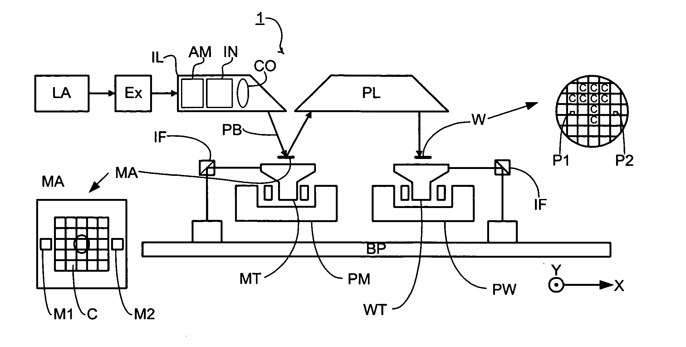
[0033]FIG. 1 schematically depicts a lithographic projection apparatus according to an embodiment of the invention. The apparatus includes an illumination system Ex, IL, configured to supply a beam PB of radiation (e.g. EUV radiation), and a radiation source LA. The apparatus also includes a first object table (mask table) MT provided with a mask holder configured to hold a mask MA (e.g. a reticle), and connected to a first positioning device configured to accurately position the mask with respect to the projection system (“lens”), item PL, with the aid of an interferometer measurement device. The apparatus further includes a second object table (substrate table) WT provided with a substrate holder configured to hold a substrate W (e.g. a resist-coated silicon wafer), and connected to a second positioning device configured to accurately position the substrate with respect to the projection system (“lens”), item PL, the a projection system (“lens”) PL (e.g. mirror group) being config...


PUM

PropertyMeasurementUnit
offset angleaaaaaaaaaa
frequencyaaaaaaaaaa

Abstract

Embodiments of the invention include an interferometer measurement system in which at least one reflective surface is arranged such that, in use, the beam path of interferometer radiation of the interferometer measurement system incident on the at least one reflective surface has an offset angle in the range of from 0.1 to 10 milliradians with respect to the normal to the at least one reflective surface. In that way, the effect of spurious radiation on the interferometer measurement system produced within the interferometer measurement system may be suppressed. In another embodiment, a parallel-sided plate is used in an interferometer measurement system to obtain a signal dependent on the angle of a beam of radiation reflected from a mirror. In that way, the flatness of the mirror can be mapped. One surface of the plate is a beam-splitter and the opposite surface of the plate is a reflector.

Description

PRIORITY INFORMATION [0001] This application claims priority from European Patent Application No. 03256381.9, filed Oct. 9, 2003, the content of which is herein incorporated by reference in its entirety. BACKGROUND [0002] 1. Field of the Invention [0003] The present invention relates to lithographic projection apparatus and methods. [0004] 2. Description of Related Art [0005] The term “patterning device” as here employed should be broadly interpreted as referring to a device that can be used to endow an incoming radiation beam with a patterned cross-section, corresponding to a pattern that is to be created in a target portion of the substrate; the term “light valve” can also be used in this context. Generally, the pattern will correspond to a particular functional layer in a device being created in the target portion, such as an integrated circuit or other device (see below). Examples of such patterning device include: [0006] 1. A mask. The concept of a mask is well known in lithogr...

Claims


Application Information

Patent Timeline
Patent Type & Authority Applications(United States)
IPC IPC(8): G03F7/20G01B9/02H01L21/027
CPCG03F7/70941G03F7/70775
Inventor MARIA BEEMS, MARCEL HENDRIKUSVAN DER PASCH, ENGELBERTUS ANTONIUS FRANSISCUS
Owner ASML NETHERLANDS BV
Why Eureka
Try Eureka