Photoconductive optical write driver for magnetic recording

a write driver and photoconductive technology, applied in the direction of mounting head within the housing, track selection/addressing details, instruments, etc., can solve the problems of limiting the data rate transmission of conventional data rate transmission, interconnection between write electronics, and the capability of existing silicon-based write drivers,

Inactive Publication Date: 2005-05-26
SEAGATE TECH LLC
View PDF8 Cites 10 Cited by
  • Summary
  • Abstract
  • Description
  • Claims
  • Application Information

AI Technical Summary

Benefits of technology

[0006] The invention meets the identified need, as well as other needs, as will

Problems solved by technology

One of the problems associated with advancing magnetic recording technology is the interconnect between the write electronics and the writer and/or reader located on the slider.
However, the bandwidth capabilities of existing silicon-based write drivers are likely to limit the data rate transmission to a few Gbits/sec.
Furthermore, the mechanical constraints associated with conventional interconnects, such as flex-on-suspension (FOS), are likely to contribute to the limitations of conventional data rate transmission.
However, there are no proven methods capable of extending recording

Method used


Image

  • Photoconductive optical write driver for magnetic recording
  • Photoconductive optical write driver for magnetic recording
  • Photoconductive optical write driver for magnetic recording

Examples


example 1

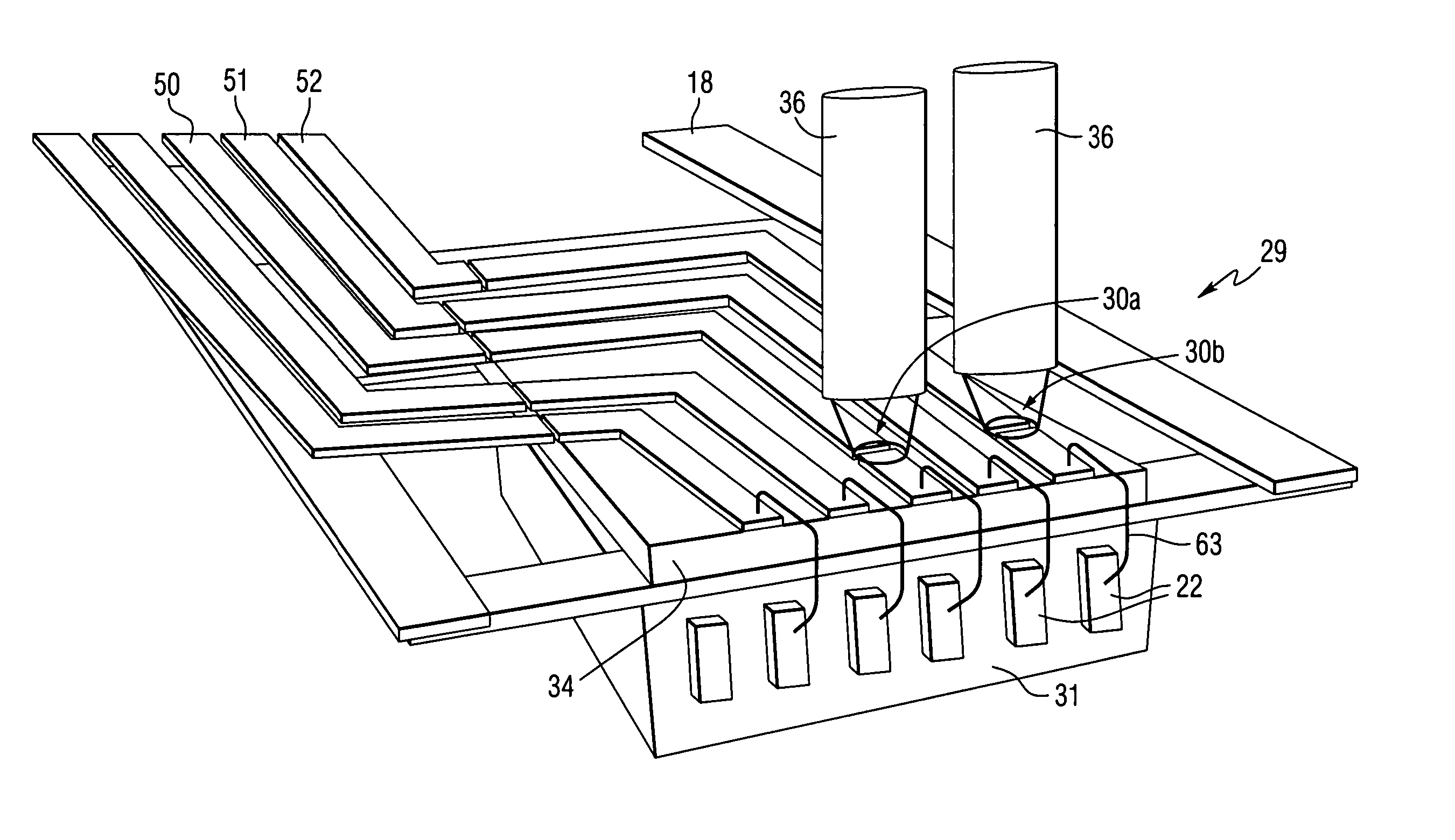
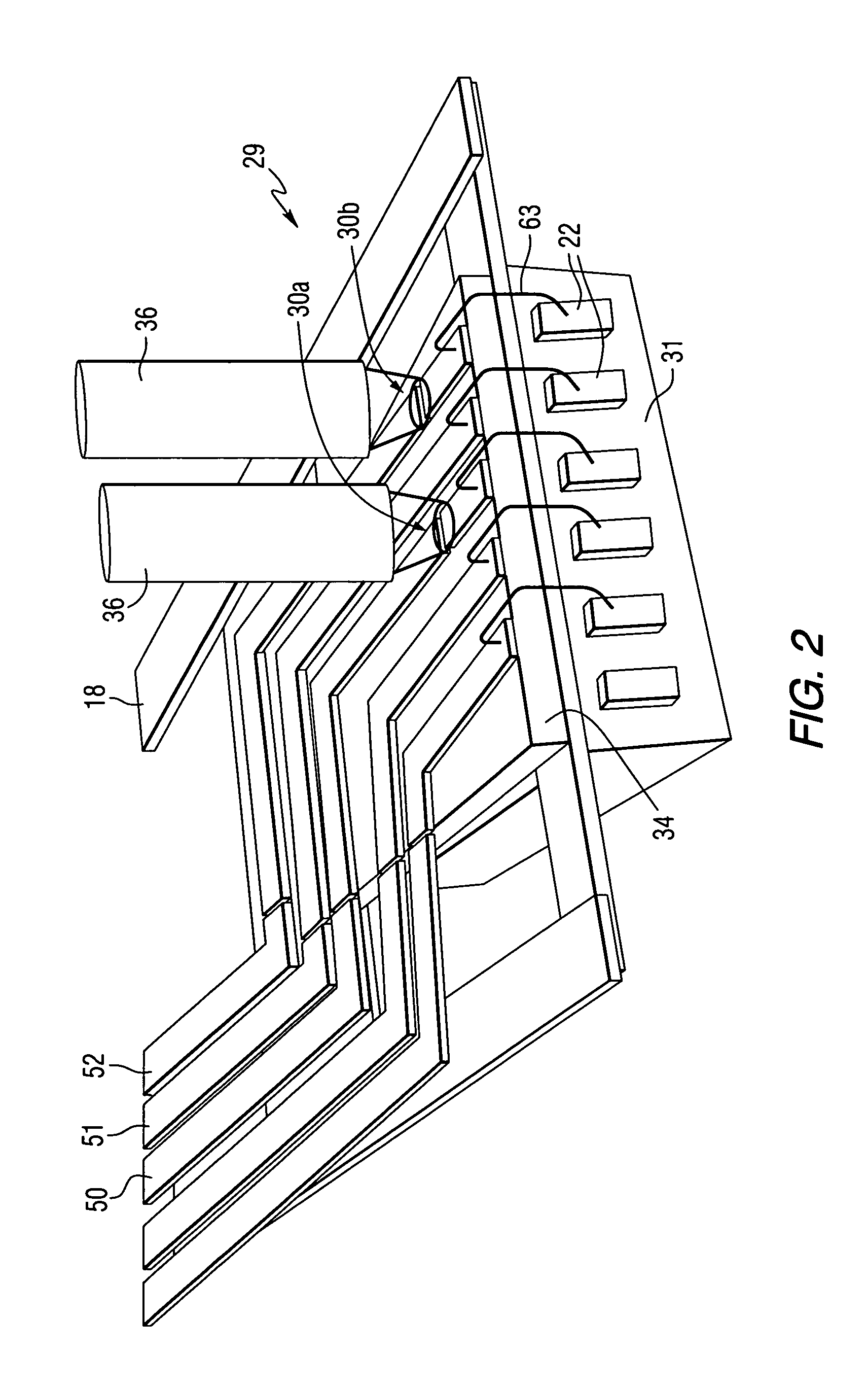
[0038] In an example of the present invention, as shown in FIG. 2, the semiconductor switch is fabricated on LT-GaAs having properties to reduce the switch resistance from infinity to about 50 Ω when the switch is illuminated with reasonable average power from a diode laser. An example of the carrier mobility, or electron mobility, of a representative LT-GaAs composition is

μn=4000 cm2V−1s−1.

For an average laser power of 20 mW, i.e. a high photogeneration rate, the resultant carrier density is

n=3×1014 cm−3.

The electrical conductivity is

σ=neμn

σ=0.19 Ω−1 cm−1,

where e is the electron charge. Inverting this equation to obtain resistivity,

ρ=5.2 Ωcm.

For a switch geometry, as shown in FIGS. 6-7, with a 1 μm thick LT-GaAs film and 100 μm long electrodes, with 100 nm between the electrodes, this yields an on-state switch resistance of R=52 Ω. Assuming that the current through the switch saturates at Vbias=5V, the current output from one of the switches in FIG. 2 is,

ISW=Vsat / Ron-...

example 2

[0039] In another example, carrier lifetimes with other LT-GaAs compositions as short as 100 fs are obtainable, however, they require increased laser power to obtain a similar switch resistance due to their lower carrier mobility and concentration values. For materials wherein μ=2000 and the carrier lifetime=100 fs, from the Example 1 calculation, R=31 kOhms for a 40 mW average power linear photogeneration rate, for materials having a 400 μm border length and 200 μm thickness. For μ=3200 cm2V−1s−1, the lifetime=50 ps. From the Example 1 calculation, R=78 kOhms. By increasing the wire thickness and the border length of the electrodes to 2 μm and 400 μm respectively, R=100 Ohms. If the laser power is doubled to 80 mW average power having a linear increase in the photogeneration rate, R=50 Ohms.

example 3

[0040] In another example, a modulator driver with 10 ps risetimes and 40 Gbit / sec data rate capability with high voltage output can be used for driving a lithium-niobate or other type of modulator, which modulates or encodes the laser output to obtain the desired optical write waveform. Lithium-niobate modulators are commercially available devices which can turn a continuous laser output of 20 mW into a square wave light output with 10 ps response times and 40 Gbit / sec data rate capability. By using the 80 ps response time of LT GaAs with a 20 mW laser, a 100 mA current can be modulated at frequencies approaching 5 GHz, which corresponds to a data rate of 10 Gbit / sec. In this example, the data rate of 10 Gbit / sec is limited by the 80 ps risetime. By turning a continuous laser output of 40 mW into a square wave light output with a 50 ps response time, a 100 mA current can be modulated at frequencies approaching 7 GHz, which corresponds to a data rate of 14 Gbits / sec. This correspond...


PUM


Abstract

A write driver for use with a magnetic recording head includes a photoconductive switch that is positioned adjacent a magnetic recording head for switching current waveforms. Both light and a DC voltage are applied to the photoconductive switch to switch the applied current waveforms. The write driver further includes means for writing to a storage medium in response to current waveforms switched by the photoconductive switch. The write driver may also include a suspension that supports at least one photoconductive switch, DC conductors for supplying a DC voltage, means for supplying light, and recording head means for writing to a storage medium.

Description

FIELD OF THE INVENTION [0001] The invention relates to recording heads for use with magnetic storage media, and more particularly, to magnetic recording head assemblies that utilize photoconductive switches located adjacent the recording head. BACKGROUND INFORMATION [0002] One of the problems associated with advancing magnetic recording technology is the interconnect between the write electronics and the writer and / or reader located on the slider. Conventional interconnects are typically 1-2 inches long and are often fabricated from polyimide materials containing imbedded circuit traces. The interconnect typically carries the write current pattern and readback signal and is physically attached to the suspension, which can act like an isolated ground plane for part of the interconnect length, or can be electrically connected to the suspension, and is therefore part of the actual circuit path. Interconnect designs, which are shorter and have ground planes, have been advanced as possib...

Claims


Application Information

Patent Timeline
IPC IPC(8): G11B5/00G11B5/012G11B5/02G11B5/09G11B5/105G11B5/127G11B5/17G11B5/31G11B5/48G11B5/49
CPCG11B5/00G11B5/012G11B5/105G11B5/127G11B5/1278G11B5/17G11B2005/0013G11B5/488G11B5/4886G11B5/4969G11B5/4984G11B2005/001G11B5/3103
Inventor CRAWFORD, THOMAS MCLENDONCOVINGTON, MARK WILLIAMCLINTON, THOMAS WILLIAM
Owner SEAGATE TECH LLC
Why Eureka
Try Eureka