Ultrafast pulse field source utilizing optically induced magnetic transformation

a pulse field and optically induced magnetic technology, applied in the direction of instruments, light beam reproducing, metal sheet head, etc., can solve the problems of short rise time, large amplitude, and inability to produce ultrafast magnetic field pulse sources with large amplitudes, and cost millions of dollars

Active Publication Date: 2005-05-26
SEAGATE TECH LLC
View PDF1 Cites 27 Cited by
  • Summary
  • Abstract
  • Description
  • Claims
  • Application Information

AI Technical Summary

Benefits of technology

[0007] The bias field can be applied by using one or more conductors, positioned near the phase transition material.

Problems solved by technology

However, one of the biggest challenges is the lack of an ultrafast magnetic field pulse source with a large amplitude (>1 Tesla) and short rise-time (<100 ps).
Conventional recording heads capable of generating large fields are typically limited by the precession frequency of the magnetization direction in the write pole, even when driven by a waveguide.
The Stanford Linear Accelerator can also deliver such short pulse fields with large amplitudes, but it cost millions of dollars.
However the application of fast heat pulses on such ordinary ferromagnetic material can only result in a demagnetizing field, where the photoexcitation terminates the fringing field for a short period.

Method used


Image

  • Ultrafast pulse field source utilizing optically induced magnetic transformation
  • Ultrafast pulse field source utilizing optically induced magnetic transformation
  • Ultrafast pulse field source utilizing optically induced magnetic transformation

Examples


Embodiment Construction

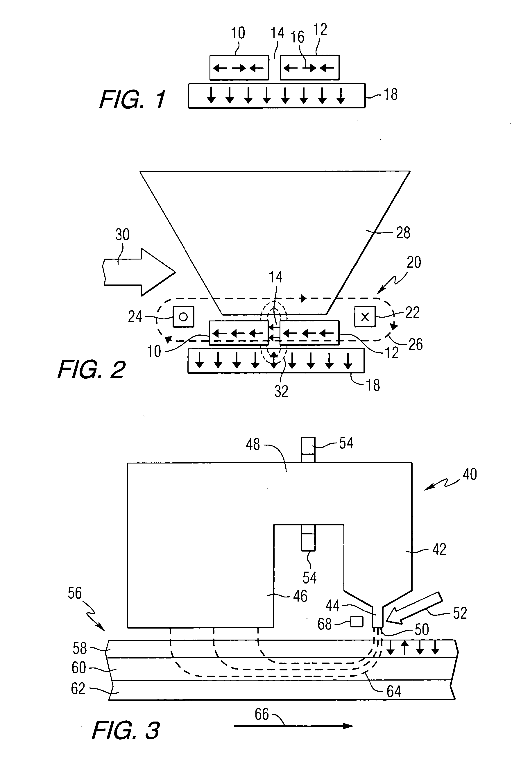
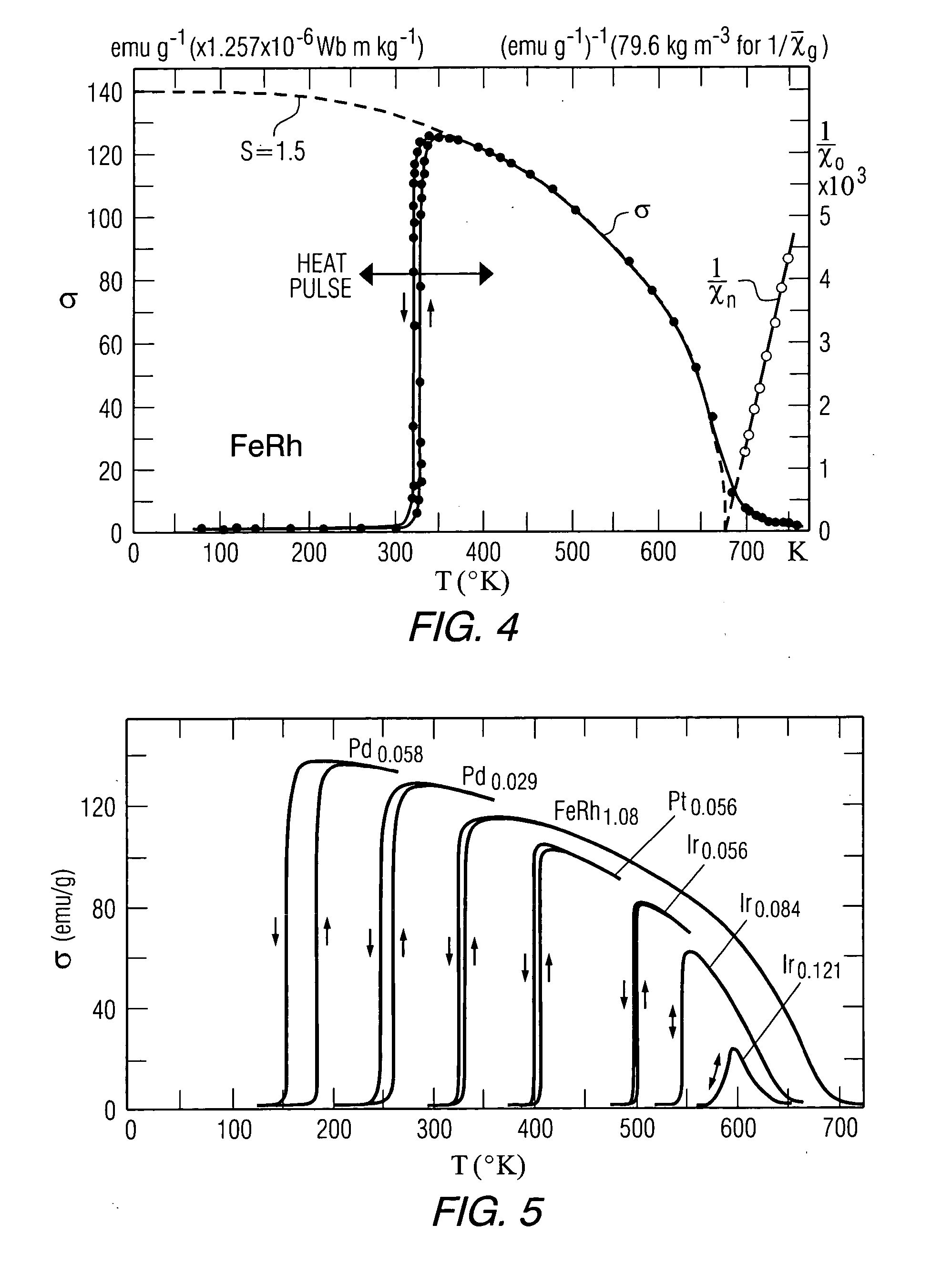
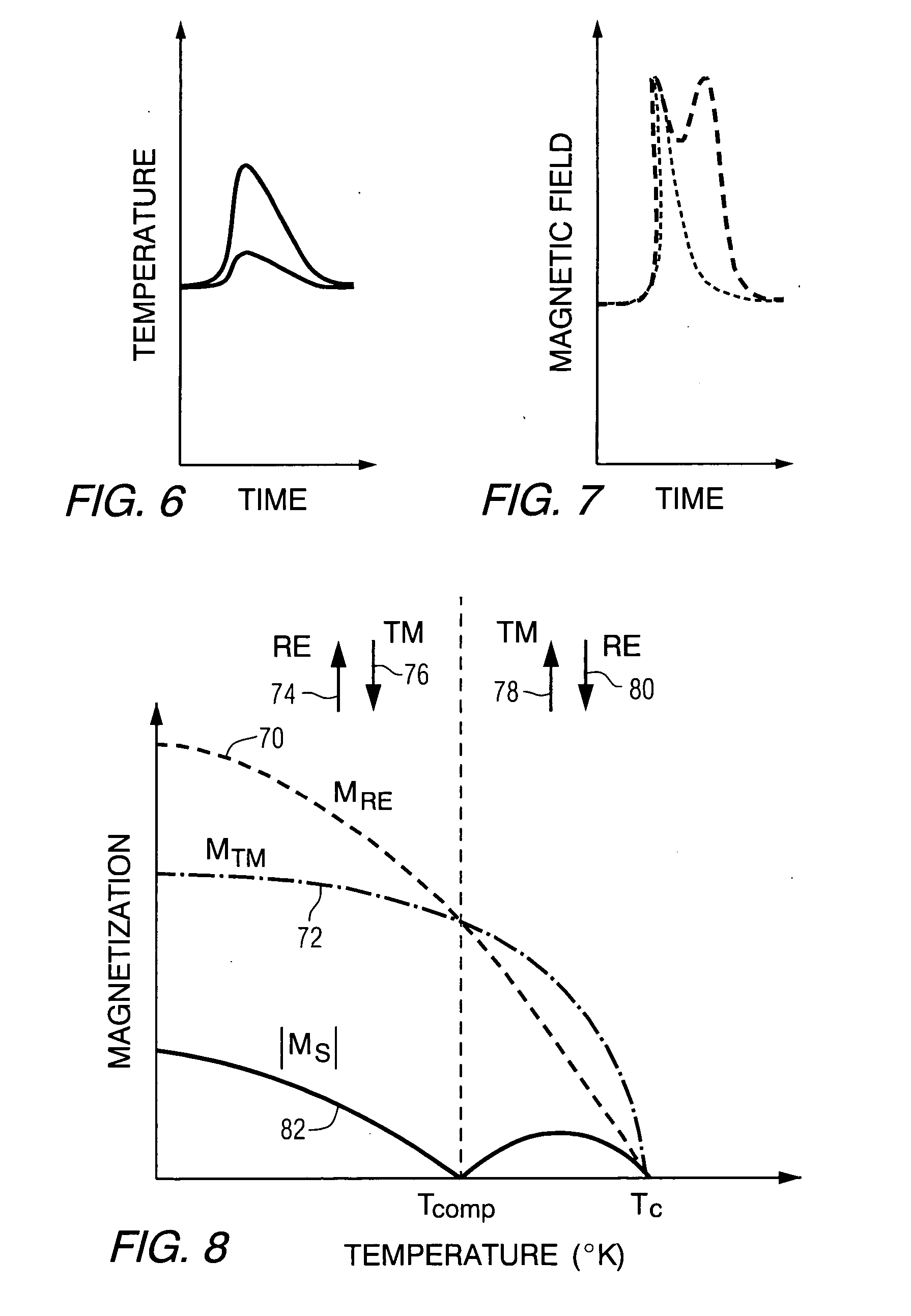
[0019] This invention provides an ultrafast pulse magnetic field transducer utilizing an antiferromagnetic-to-ferromagnetic (AFM-FM) transition on an ultrashort time scale. The antiferromagnetic-to-ferromagnetic transition can be optically induced. Magnetic materials such as, FeRh or FeRhX (where X can be a transition metal, such as Pd, Pt, Ir, Ru, Re or Os, etc.), are antiferromagnetic at room temperature, and become ferromagnetic when heated above a critical temperature TN. For the purposes of this description, these materials are referred to as phase transition materials. The transducers of this invention apply an ultrashort heat pulse to the phase transition material to generate an ultrafast fringing field. The heat pulse can be applied for a brief time period of for example −10 sec. Electromagnetic radiation such as visible, ultraviolet or infrared light can be directed onto the phase transition material to provide the heat pulse. One example of the transducer includes an open ...


PUM

PropertyMeasurementUnit
time periodaaaaaaaaaa
fall timeaaaaaaaaaa
fall timeaaaaaaaaaa

Abstract

A magnetic field transducer includes a phase transition material exhibiting a change from an antiferromagnetic phase to a ferromagnetic phase when heated above a critical temperature, means for applying a magnetic bias field to the phase transition material, and means for heating the phase transition material above the critical temperature. Magnetic recording heads that include the transducer and magnetic disc drives that include the magnetic recording heads are also described. A method of producing a magnetic field pulse including applying a magnetic bias field to a phase transition material, and heating the phase transition material to cause the phase transition material to change from an antiferromagnetic phase to a ferromagnetic phase, is also provided. The phase transition material can comprise a rare earth-transition metal alloy, where the alloy is heated above a compensation temperature.

Description

FIELD OF THE INVENTION [0001] This invention relates to transducers for producing magnetic fields, and more particularly to such transducers that can be used to produce magnetic field pulses. BACKGROUND OF THE INVENTION [0002] With the rapid increase of areal density and data rate for magnetic recording systems, the examination of high frequency switching dynamics of the recording medium becomes even more important. However, one of the biggest challenges is the lack of an ultrafast magnetic field pulse source with a large amplitude (>1 Tesla) and short rise-time (<100 ps). Conventional recording heads capable of generating large fields are typically limited by the precession frequency of the magnetization direction in the write pole, even when driven by a waveguide. Other options like high bandwidth co-planar waveguides have difficulty generating a large amplitude pulse field. Optical pulse excitation of a Schottky barrier can deliver an ultrafast pulse, but the amplitude is w...

Claims


Application Information

Patent Timeline
Patent Type & Authority Applications(United States)
IPC IPC(8): G11B5/00G11B5/147G11B11/105G11C11/16
CPCG11B11/10534G11B2005/0008G11C11/16G11B2005/0034G11B2005/0021G11C11/1675G11C11/161
Inventor JU, GANPINGKARNS, DUANEAMBROSE, THOMAS F.VAN DE VEERDONK, RENE JOHANNES MARINUS
Owner SEAGATE TECH LLC
Why Eureka
Try Eureka