Dual station applicator wheels for filling cavities with metered amounts of particulate material

a technology of particulate material and applicator wheel, which is applied in the direction of tobacco, liquid handling, packaging goods types, etc., can solve the problems of difficult to achieve 100% filling of the cavity in the article, and difficulty in achieving consistent accurate filling of the desired cavity with granular particles, etc., to achieve the effect of accurate filling and faster particle transfer

Inactive Publication Date: 2005-05-26
PHILIP MORRIS USA INC
View PDF9 Cites 20 Cited by
  • Summary
  • Abstract
  • Description
  • Claims
  • Application Information

AI Technical Summary

Benefits of technology

[0007] The filling system adjacent to each rotating wheel includes a vertical drop chute with a height that is determined such that the particles accelerate under gravity through the drop chute and are traveling at approximately the surface speed of the rotating wheels when the particles enter the filling chamber. The filling chamber includes openings at the top to receive the particles from the vertical drop chute, at the bottom so that excess particles can drop out of the bottom of the filling chamber to be captured and recycled, and on the side of the filling chamber facing the rotating wheel. The side of the filling chamber opposite from the rotating wheel is provided with air inlets to allow cross air flow through the filling chamber and into the pockets of the rotating wheel. Each filling chamber can also be provided with optional deflector vanes to assist in deflecting the particles into the wheel pockets. As particles enter the top of the filling chamber from the vertical drop chute, cross air flow produced by the wheel vacuum and the inlets in the side of the filling chamber opposite from the wheel, direct the particles toward the wheel. The vacuum created by the stationary or rotatable internal vacuum plenum pulls the particles into the wheel pockets until the pockets are full. A scraper can be provided at the bottom of the filling chamber to scrap the outer surface of the wheel, thereby ensuring that each wheel pocket is accurately filled. A stationary air jet can also be provided inside the rotating wheel at a position adjacent the end of the vacuum plenum in the direction of rotation of the rotating wheel. The air jet directs a blast of air radially outwardly to assist in rapidly emptying each pocket of the rotating wheel as it rotates past the end of the vacuum plenum.
[0008] The cavities to be filled with the granules or particles are passed underneath each rotating applicator wheel and their movement is synchronized with the movement of the rotating wheels so that each cavity to be filled coincides with a pocket on the outer surface of each rotating wheel. A vacuum rail for conveying the article or articles having the cavities to be filled can also be provided. The material in which the cavities are formed can be porous material that allows the vacuum from the vacuum rail to create a negative pressure in the cavities. An example of such a porous material is the paper plug wrap used in forming cigarette filter rods. The vacuum rail can also be provided with separate chambers having higher and lower amounts of vacuum such that a chamber having the higher vacuum coincides with the cavity that is being filled with particles from the rotating wheel, while the other areas of the article coincide with the chambers having lower vacuum. The use of a high vacuum section in the vacuum rail at the point of particle transfer, and low vacuum at other points allows for quicker transfer of particles at the transfer point without having to adjust the rate at which the cavities are moved underneath the rotating wheel.

Problems solved by technology

During high speed mass production of such articles it is difficult to achieve consistent accurate filling of the desired cavities with the granular particles.
This arrangement makes it difficult to achieve 100% fill of the cavities in the article receiving particulate material from the transfer wheel.

Method used


Image

  • Dual station applicator wheels for filling cavities with metered amounts of particulate material
  • Dual station applicator wheels for filling cavities with metered amounts of particulate material
  • Dual station applicator wheels for filling cavities with metered amounts of particulate material

Examples


Embodiment Construction

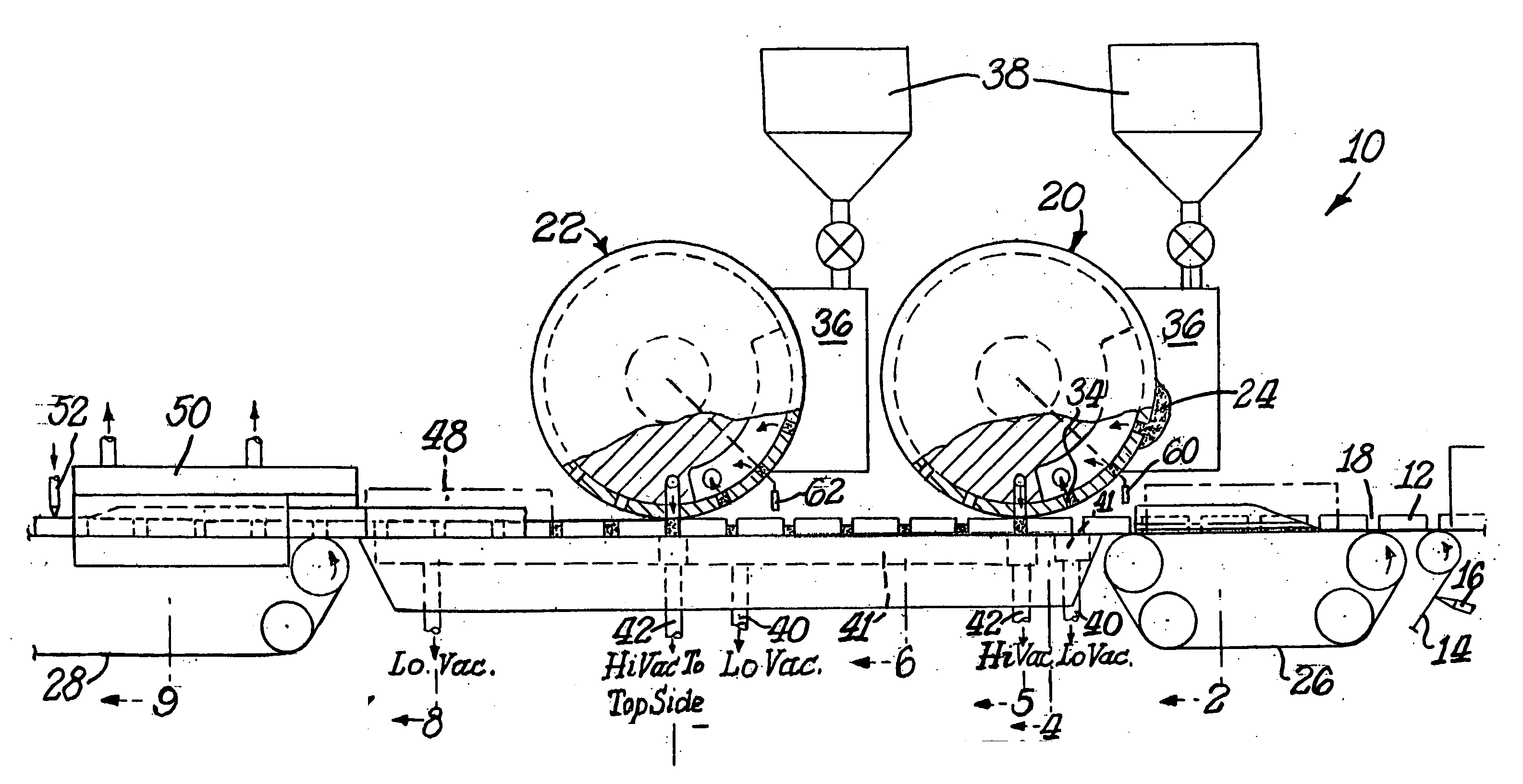
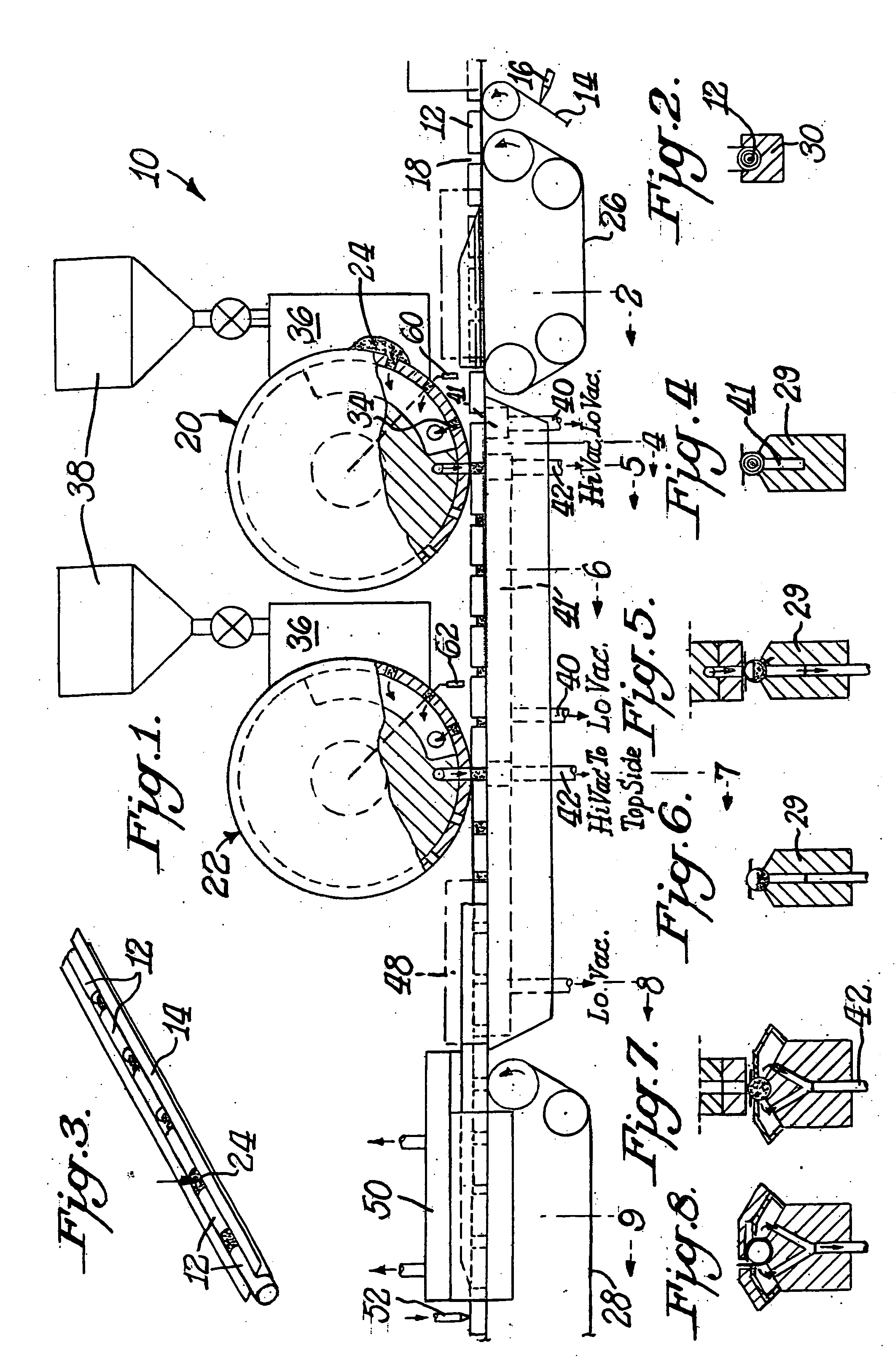
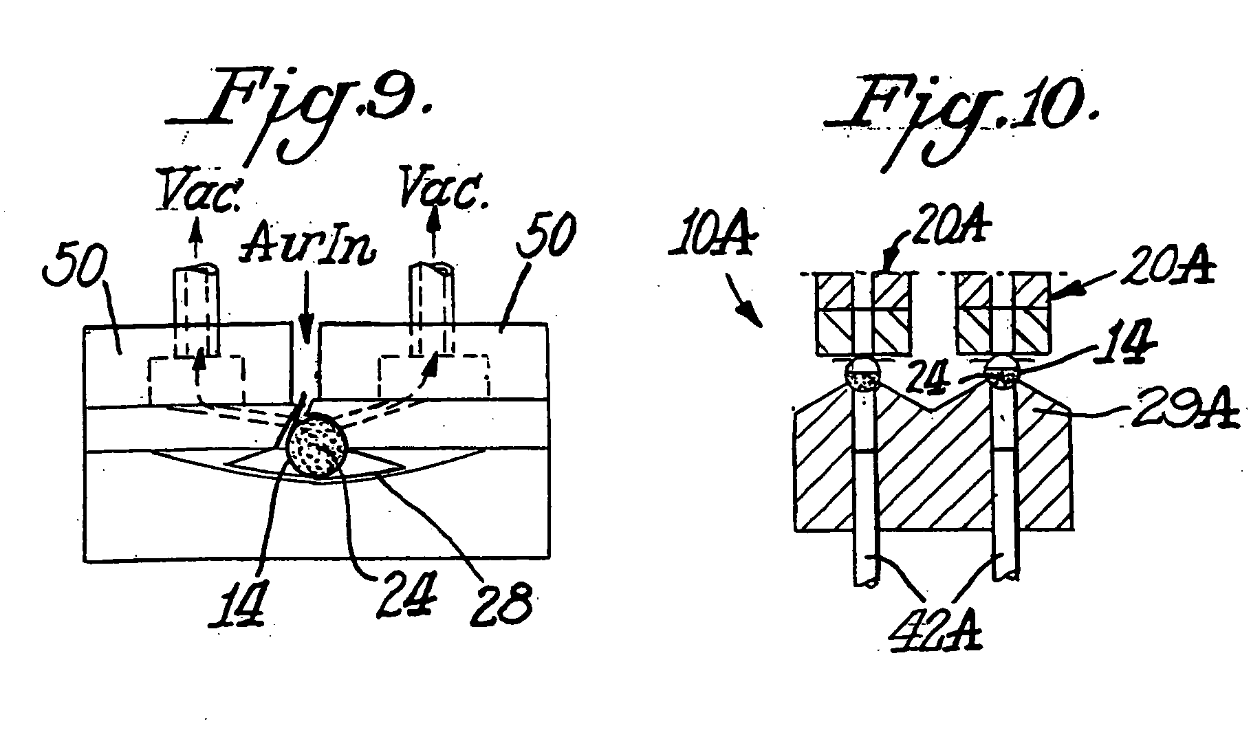
[0021] The present invention provides a system useful for transferring accurately metered volumes of particles to cavities in an article or articles being produced at a high rate during mass production of the articles. The system includes upstream and downstream applicator wheels each of which rotates around a central stationary drum or vacuum plenum defining at least one vacuum chamber. A series of pockets are defined along an outer circumferential surface of each rotating applicator wheel between the outer periphery of the wheel and a perforated band or screen that is clamped against the inner periphery of the wheel, to both accurately meter and transfer predetermined amounts of granules or particles into cavities of one or more articles. Accurate metering and transfer of particles is achieved through the use of dual filling stations each of which includes a filling system that uses gravitational acceleration of the particles and cross air flow to achieve rapid filling of the pock...


PUM

PropertyMeasurementUnit
vacuumaaaaaaaaaa
speedaaaaaaaaaa
flexibleaaaaaaaaaa

Abstract

Apparatus and method for filling spaced apart cavities with particulate material include a transport for moving the cavities along a path of travel. The cavities are partially filled with particulate material at an upstream location while applying vacuum underneath each cavity during such partial filling. The partially filled cavities are then completely filled with a downstream deposit of particulate material while applying vacuum to the upper sides of each cavity during such filling. The combination of vacuum applied underneath the cavity during partial fill and vacuum applied to the top sides of the cavity during complete fill produces approximately 100% cavity fill with minimal extraneous scatter of particulate material.

Description

BACKGROUND OF THE INVENTION [0001] The present invention generally relates to methods and apparatus for accurately delivering precisely metered amounts of particulate material from dual station applicator wheels in a repetitive manner during high speed manufacture of particulate-filled articles of manufacture, and more particularly to precise and repetitive delivery of granular carbon from dual station applicator wheels into spaces presented during the manufacture of plug-space-plug cigarette filters. [0002] Certain articles of manufacture such as carbon cigarette filters, individual-sized packets of granular food products or condiments, capsuled pharmaceuticals, ammunition and the like require repetitive placement of precisely metered charges of particulate matter at some location along the production-line procession of the articles. During high speed mass production of such articles it is difficult to achieve consistent accurate filling of the desired cavities with the granular pa...

Claims


Application Information

Patent Timeline
Patent Type & Authority Applications(United States)
IPC IPC(8): B65B1/36
CPCB65B1/366A24D3/0225
Inventor SMITH, BARRY S.SPIERS, STEVESTRAIGHT, JEREMYTHOMPSON, JANETERCELEBI, AHMETGARTHAFFNER, MARTIN T.ROGERS, LISA
Owner PHILIP MORRIS USA INC
Why Eureka
Try Eureka