Field electron emitting device

a field electron and emitting device technology, applied in the manufacture of discharge tube main electrodes, electrode systems, electric discharge tubes/lamps, etc., can solve the problems of diamond's diamond emission characteristics being poorer than the excellent electron emission characteristics of cnt, and the sharpness of the tip end thereof being evaluated as the diameter of a cross section,

Inactive Publication Date: 2005-06-02
JAPAN SCI & TECH CORP +1
View PDF3 Cites 11 Cited by
  • Summary
  • Abstract
  • Description
  • Claims
  • Application Information

AI Technical Summary

Problems solved by technology

However, when a metal shaped like a needle is used as an electron emitting source, the sharpness of the tip end thereof, when evaluated as the diameter of a cross section, cannot exceed several hundred nm.
That is, there is a limit in enhancing the aspect ratio in the case of an electron emitting source made of metal.
Although diamond exhibits better electron emission characteristics, as compared with an electron emitting source in which a metal material is used, the electron emission characteristics of diamond are poorer than the excellent

Method used


Image

  • Field electron emitting device
  • Field electron emitting device
  • Field electron emitting device

Examples


example

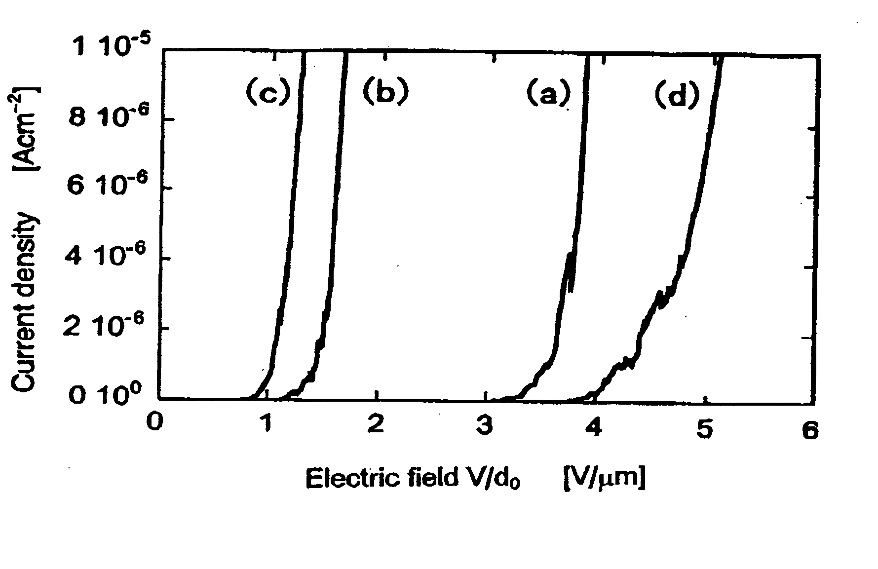
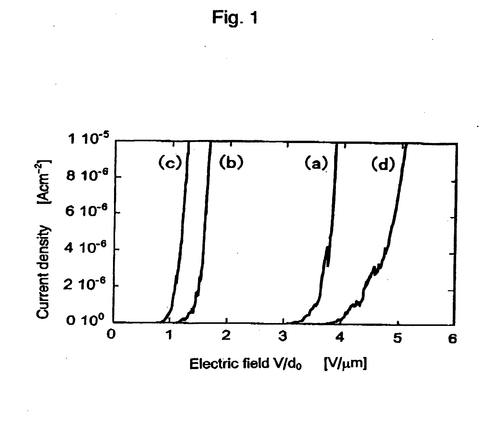
[0026] A single-walled carbon nanohorn aggregate of which average diameter was 80 nm was obtained by irradiation of graphite with CO2 laser. The single-walled carbon nanohorn aggregate was placed in ethanol and dispersed by irradiation with ultrasonic wave. Thereafter, the dispersed carbon nanohorn aggregate was suction-filtrated by a ceramic filter of which pore diameter was 200 nm. The deposit collected on the filter was dried and a single walled carbon nanohorn aggregate film was obtained. The thickness of the film was no more than 200 μm and the density thereof was no more than 0.3 g / cm3. An electron emitting experiment was carried out by using the obtained singe-walled carbon nanohorn aggregate as a sample (a).

[0027] As samples for comparison, films of (b) a single-walled carbon nanotube (SWNT), (c) dosed multi-walled carbon nanotube (closed MWNT), (d) multi-walled carbon nanotube produced by using a metal catalyst in the production process thereof (catal MWNT), were formed by...


PUM


Abstract

A novel field electron emitting device characterized in that a main portion of an electron emitting source for emitting electrons by an electric field is made of a carbon nanohorn. The field electron emitting device is high in electron emitting efficiency and excellent in productivity.

Description

TECHNICAL FIELD [0001] The present invention relates to a field electron emitting device. More specifically, the present invention relates to a novel field electron emitting device in which a carbon nanohorn is used and which is useful for a flat panel display and the like. BACKGROUND ART [0002] Conventionally, in a flat panel display (FPD) which utilizes field electron emission characteristics, a metal having a relatively small work function, which metal may be of various types, is generally used for an electron emitting source of an electron emitting device. [0003] It is considered that an electron emitting source preferably has a tip end, which is of a sharp conical shape, and has a relatively large aspect ration (length / diameter of cross section) in order to achieve a higher efficiency in emitting electrons at a lower voltage. However, when a metal shaped like a needle is used as an electron emitting source, the sharpness of the tip end thereof, when evaluated as the diameter of...

Claims


Application Information

Patent Timeline
IPC IPC(8): H01J1/304
CPCB82Y10/00H01J2201/30469H01J1/3048H01J1/304H01J1/30
Inventor IIJIMA, SUMIOYUDASAKA, MASAKOLASZLO, FORROSLAVEN, GARAJBONARD, J.-M.
Owner JAPAN SCI & TECH CORP
Why Eureka
Try Eureka