Digital ophthalmic workstation

a workstation and digital technology, applied in the field of providing computer-generated aids for ophthalmic surgery, can solve the problems of difficult observation, difficult advice, difficult excision or suture, etc., and achieve the effects of reducing the effect of glare, wide dynamic range, and reducing the saturation of highlights

Inactive Publication Date: 2005-06-02
3D VISION SYST
View PDF19 Cites 107 Cited by
  • Summary
  • Abstract
  • Description
  • Claims
  • Application Information

AI Technical Summary

Benefits of technology

[0009] In other embodiments of the invention, a system that can respond to a wide dynamic range of illumination is provided to reduce the saturation of highlights and thereby to reduce the effects of glare. In some embodiments of the invention, the wide dynamic range is achieved using a video camera with adjustable sensitivity and using corresponding scaling techniques. In other embodiments, the wide dynamic range is achieved by illuminating the first eye with a variable brightness light source. The brightness of the light source may be adjusted by determining the illumination level at specified points in the captured image and then adjusting the illumination level. In some embodiments of the invention, this adjustment may be made with a feedback loop.
[0010] In various embodiments of the invention, the captured image may be processed to change the resolution, contrast, brightness, magnification and color of the image. The image may also be processed to enhance an edge in the image. In some embodiments of the invention, a portion of the image of the eye may be magnified at higher magnification level than another portion of the eye. The portion of the eye with the higher magnification level is shown in greater detail, while the rest of the image provides awareness to a surgeon of the situation outside of the highly magnified portion. In other embodiments of the invention, the eye may be illuminated with laser light. An opaque screen is provided to shield operating room personnel from exposure to the light and the surgeon may view the image of the eye on the display monitor, rather than directly. Thus, danger to sensitive tissues of operating room personnel may be reduced.

Problems solved by technology

During the operation, the ink tends to be washed away because of frequent irrigations necessary to keep the surface of the eye moist, making such excisions or sutures difficult.
Advisors in remote locations may not be able to observe the surgical subject, making it difficult to provide advice.
Additionally, the level of expertise available may not be able to provide proper guidance.

Method used


Image

  • Digital ophthalmic workstation
  • Digital ophthalmic workstation
  • Digital ophthalmic workstation

Examples


Embodiment Construction

[0026] In various embodiments of the invention, a method is provided for visualization of the structures of the eye. Video processing and digital image processing techniques enhance the image improving an ophthalmologist's ability to see the structures clearly. In specific embodiments of the invention, a computer is employed to process the captured eye images and to overlay information that is useful for the ophthalmologist for performing therapeutic procedures on the eye.

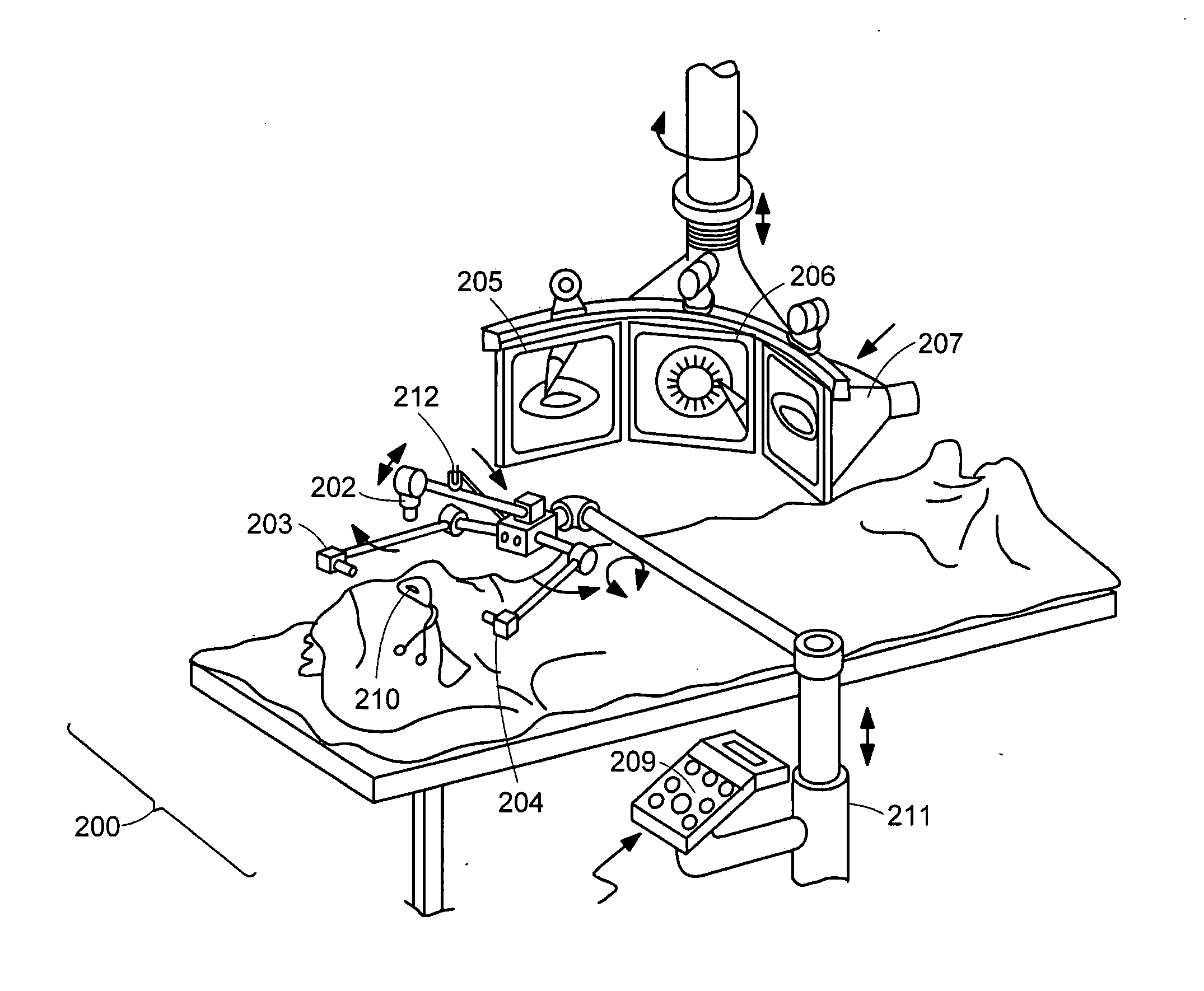
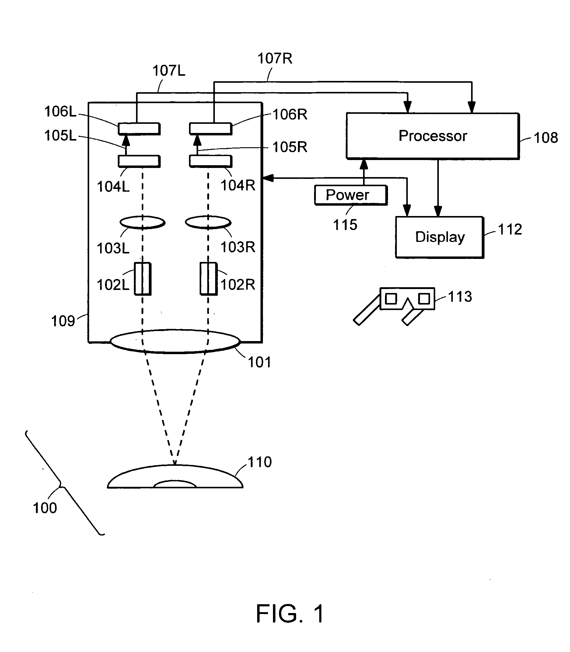
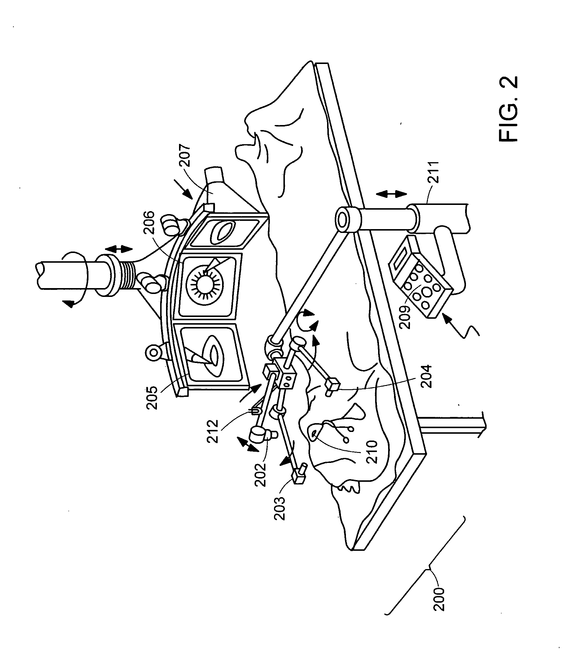
[0027]FIG. 1 is a block diagram of a stereoscopic surgical microscopic system 100, in accordance with one embodiment of the invention. Such a system may be used in, but not limited to, ophthalmic surgery, cerebral surgery, cosmetic surgery, and ear, nose and throat surgery. The system includes at least one stereoscopic video camera 109 for generating a video signal(s) representing a stereoscopic view pair of a surgical subject 110. The video signal is provided to one or more displays 112. An intelligence component...


PUM


Abstract

A method of providing visual documentation and information for a surgical procedure. The method includes, providing at least one video camera for generating a video signal in a digital format, capturing an image of an eye and displaying the image on a monitor. A first template is created having a graphical content pertinent to the eye. The first template is displayed such that the first template is overlaid contemporaneously with the image of the eye on a display monitor.

Description

[0001] This application is a continuation-in-part application of a U.S. patent application entitled “A System and Method of Providing Visual Documentation during Surgery,” Ser. No. 10 / 265,303, filed Oct. 4, 2002. This application also claims priority from both U.S. provisional patent application Ser. No. 60 / 327,323, filed Oct. 5, 2001, entitled “An Intelligent Ophthalmic Microsurgical System” and U.S. provisional patent application Ser. No. 60 / 348,545, filed Jan. 16, 2002, entitled “A Failsafe, Multiview, Electro-optical, Cluster for Ophthalmic Microsurgery.” Each of the patent applications described in this paragraph is hereby incorporated by reference in its entirety.TECHNICAL FIELD [0002] The present invention relates to a method and device for providing computer-generated aids for ophthalmic surgery, and more particularly, for visualization of ophthalmic structures. BACKGROUND ART [0003] During an ophthalmic surgical procedure using a standard operating microscope, a surgeon may...

Claims


Application Information

Patent Timeline
Patent Type & Authority Applications(United States)
IPC IPC(8): A61B19/00H04N13/239
CPCA61B3/13A61B3/158H04N13/0438H04N13/0239H04N13/0434A61B19/52A61B90/36H04N13/337H04N13/341H04N13/239
Inventor MILLER, DAVIDBLANCOBURNS, STEVE K.STEGMANN, ROBERTRAO, RAMGOPAL
Owner 3D VISION SYST
Why Eureka
Try Eureka