Reflective light coupler

a coupler and reflector technology, applied in the field of optical systems, can solve the problems of loss of approximately 70% of the generated light, loss of flexibility, and general inefficiency of methods, and achieve the effect of high coupling efficiency and high efficiency of optical coupling

Inactive Publication Date: 2005-06-02
3M INNOVATIVE PROPERTIES CO
View PDF99 Cites 103 Cited by
  • Summary
  • Abstract
  • Description
  • Claims
  • Application Information

AI Technical Summary

Benefits of technology

[0007] One particular approach to constructing a high intensity illumination system is to couple light from individual light emitting diodes (LEDs) to respective optical fibers. The respective optical fibers may then be bundled to form a remote illumination output. A reflective coupler between each LED and its respective optical fiber provides highly efficient optical coupling. The shape of the reflective coupler is important for maintaining a high coupling efficiency between the LED and its optical fiber.

Problems solved by technology

These methods are generally inefficient, with approximately 70% of the generated light being lost in some cases.
In a single light guide approach, a light guide having a large enough diameter to capture the amount of light needed for bright lighting applications becomes thick and, therefore, loses flexibility.
Laser sources, however, are expensive and typically produce light at a single wavelength, which is less useful where the requirement is for broadband illumination.

Method used


Image

  • Reflective light coupler
  • Reflective light coupler
  • Reflective light coupler

Examples


Embodiment Construction

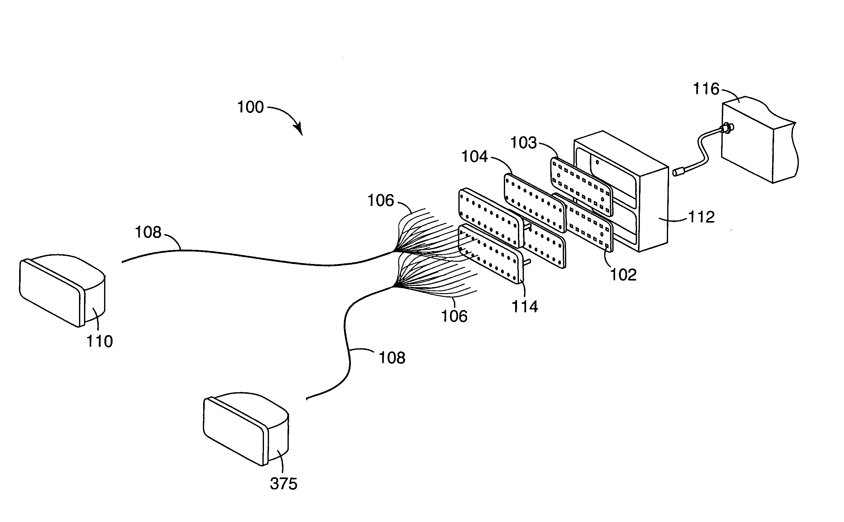
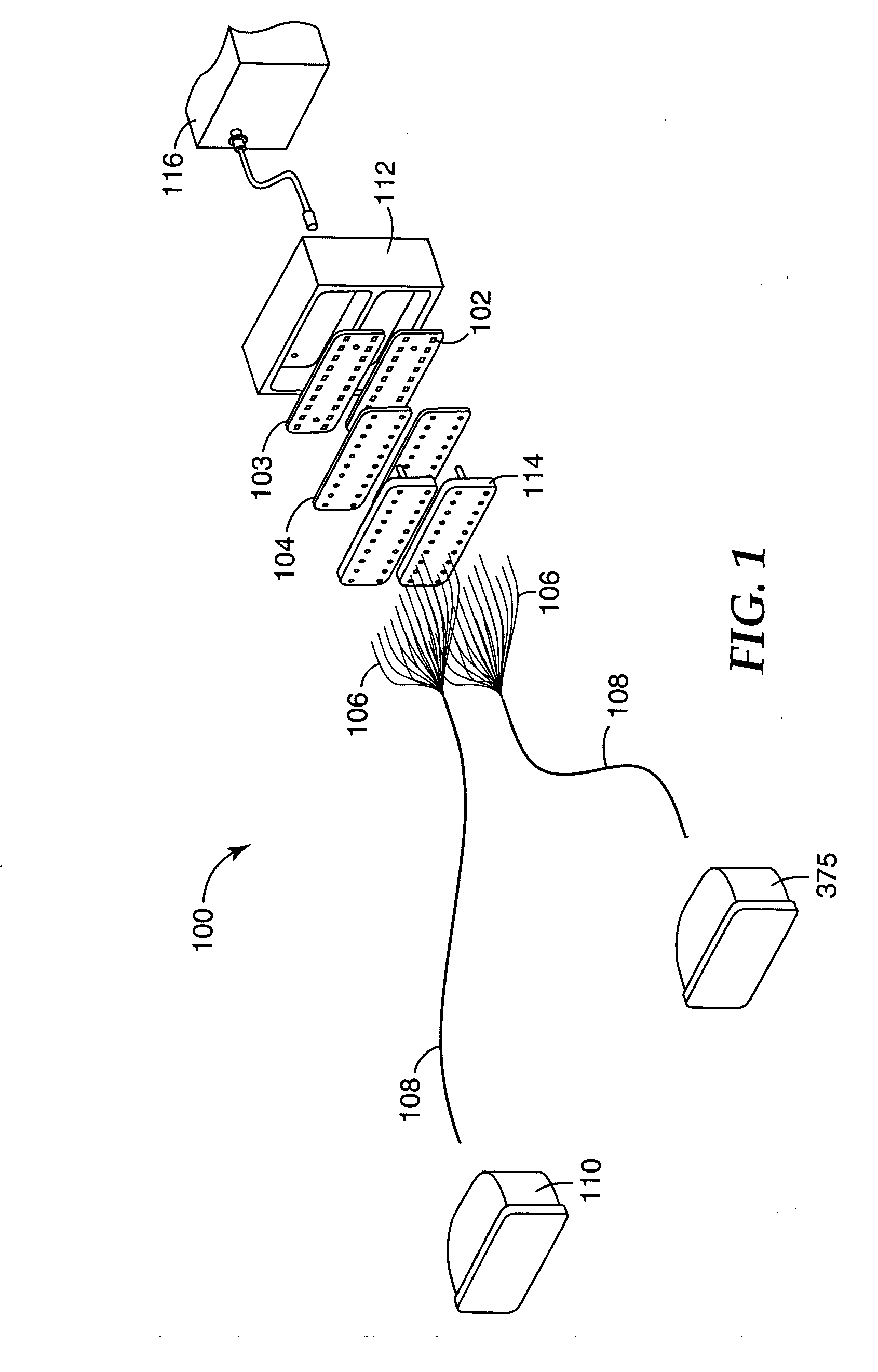
[0024] The present invention is applicable to optical systems and is more particularly applicable to light collection and management systems useful for illuminating a target with light from one or more light emitting diodes (LEDs).

[0025] LEDs with higher output power are becoming more readily available, which opens up new applications for LED illumination with white light. Some applications that may be addressed with high power LEDs include projection and display systems, machine vision systems and camera / video applications, and even distance illumination systems such as car headlights.

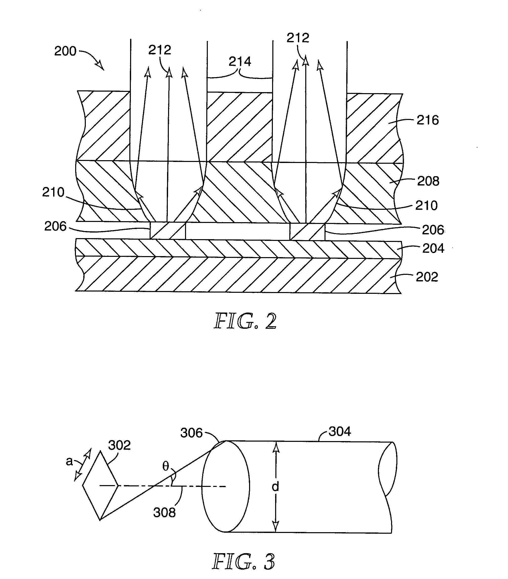
[0026] LEDs typically emit light over a wide angle, and so one of the challenges for the optical designer is the efficient collection of the light produced by an LED and the direction of the collected light to a selected target area. In some applications, the target area is the input to a light guide, such as an optical fiber, so that the light may be used for remote illumination. For example, some ...


PUM

PropertyMeasurementUnit
diameteraaaaaaaaaa
refractive indexaaaaaaaaaa

Abstract

An illumination system has individual light emitting diodes (LEDs) that are optically coupled via reflective couplers to respective optical fibers. The respective optical fibers may then be bundled. The shape of the reflective coupler may be selected to increase the coupling efficiency between the LED and its optical fiber. The reflective coupler may be formed as an aperture through a sheet, having a first shape at the input side and a second shape, different form the first shape, at the second side. The reflective coupler may be formed as an aperture through a body, where at least a first portion of the interior surface of the aperture conforms to a two-dimensional (2-D) surface and at least a second portion of the interior surface conforms to a three-dimensional (3-D) surface.

Description

RELATED PATENT APPLICATIONS [0001] The following co-owned and concurrently filed U.S. patent applications are incorporated herein by reference: “ILLUMINATION SYSTEM USING A PLURALITY OF LIGHT SOURCES”, having Attorney Docket No. 58130US004; “MULTIPLE LED SOURCE AND METHOD FOR ASSEMBLING SAME”, Attorney Docket No. 59376US002; “SOLID STATE LIGHT DEVICE”, having Attorney Docket No. 59349US002; “ILLUMINATION ASSEMBLY”, having Attorney Docket No. 59333US002; “PHOSPHOR BASED LIGHT SOURCES HAVING A POLYMERIC LONG PASS REFLECTOR”, having Attorney Docket No. 58389US004; and “PHOSPHOR BASED LIGHT SOURCES HAVING A NON-PLANAR LONG PASS REFLECTOR”, having Attorney Docket No. 59416US002.FIELD OF THE INVENTION [0002] The invention relates to optical systems, and more particularly to couplers for coupling light from a broadly emitting light source to a target such as an optical fiber. BACKGROUND [0003] Illumination systems are used in a variety of applications. Home and industrial applications ofte...

Claims


Application Information

Patent Timeline
Patent Type & Authority Applications(United States)
IPC IPC(8): G02B6/42G02B27/09H01L33/00H01L33/60
CPCG02B6/4204G02B6/4214G02B6/4249G02B19/0028G02B19/0066G02B19/0023G02B27/0983G02B6/42
Inventor SIMBAL, JOHN J.
Owner 3M INNOVATIVE PROPERTIES CO
Why Eureka
Try Eureka